FAULT MODES
MICROTECH 2300 UNIT CONTROLLERDAIKIN APPLIED
14
Fault Modes
Brownout
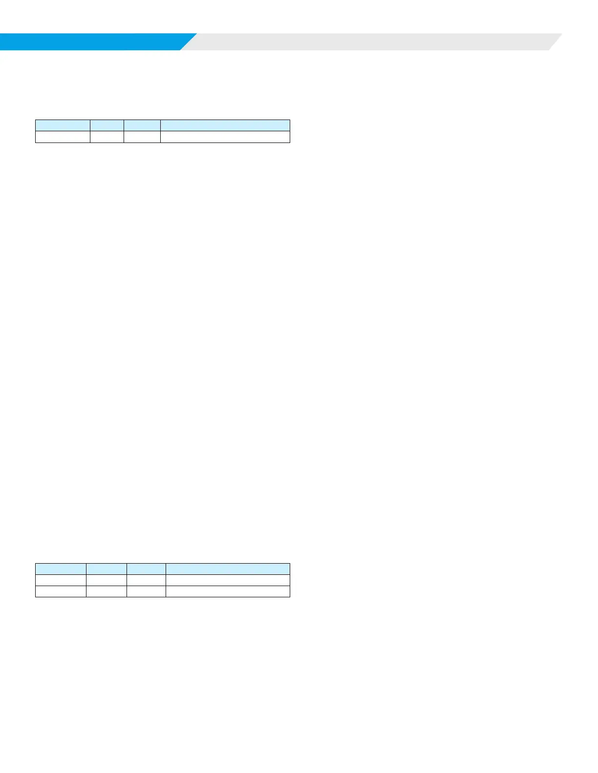
LED Activity Type Color Description
1 Flash Fault Yellow Compressor Low Voltage Brownout
Brownout condition is provided to protect the water source heat
pump’s motor electrical damage due to low voltage conditions.
The MT2300 unit controller is designed to monitor the 24VAC
power supply to the board. If the line voltage supplied to the
water source heat pump drops, the 24VAC supply to the control
board will also drop. When the line voltage supplied to the unit
drops below approximately 80% of the unit nameplate rated
value, the controller goes into brownout condition. The controller
remains in brownout condition until line voltage returns to
approximately 90% of the unit nameplate value.
When in brownout condition, thermostat and control inputs have
no aect upon unit operation. Remote shutdown and brownout
conditions have the same level of priority. See Table 6 on page
16.
When the unit is in brownout condition the following occurs:
1. The compressor de-energizes.
2. The IV/PR (H6) output will change state. (On to O / O to
On).
3. The fan de-energizes.
4. Alarm terminal (TB4-ALM) energizes (fault). TB4-ALM will
close to AB4-COM to indicate an alarm signal.When the
line voltage supplied to the unit returns to acceptable levels
(90% of nameplate) the controller returns to the current
mode.
High / Low Pressure Faults (HP/LP)
Normally closed high and low refrigerant pressure switches help
protect the water source heat pump from excessively high or
low refrigerant pressures. The MT2300 unit controller monitors
these switches individually. If the compressor is running and the
HP circuit is open, the controller enters a pressure fault mode. If
the LP circuit is open after a time delay (default of 30 seconds,
adjustable if a communication module is present) the controller
enters a low pressure fault mode.
LED Activity Type Color Description
1 Flash Fault Red Compressor #1 High Pressure
2 Flash Fault Red Compressor #1 Low Pressure
See Table 6 on page 16.
When the unit is in high or low pressure fault modes the following
occurs:
1. The compressor de-energizes.
2. The IV/PR (H6) output will change state. (On to O / O to
On).
3. The fan de-energizes.
4. The alarm terminal (TB4-ALM) energizes (fault). TB4-ALM
will close to TB4-COM to indicate an alarm signal.
High Pressure/Low Pressure Reset
After the HP circuit is closed, the unit does not return to normal
operation until the alarm is manually reset. The unit is locked out
in this manner until the unit can be serviced.
The alarm is reset by a short interruption of unit power, by holding
down the tenant override button for more than 10 seconds, or via
the Building Automation System (BAS).
Low Suction Temperature Fault
Heating
1. When the suction line temperature falls below 28°F
(standard range) or 6.5°F (Geothermal) the compressor
output is disabled.
2. The control will attempt to recover from a low suction
temperature condition by defrosting the water heat
exchanger (coaxial coil). See “Defrost Sequence of
Operation (Heating)”
3. When the suction line temperature increases by the Low
Temp Protect Di (the default is 8°F) degrees.
4. The compressor is available for heating when the
compressor minimum o timer has expired.
Defrost Sequence of Operation (Heating)
1. Immediately turn o the compressor if operating in the
cooling or dehumidication modes.
2. The reversing valve output is de-activated, placing the
reversing valve in the cooling mode and moving warm
refrigerant to the coax coil.
3. Fan speed is not changed, however “Heat Stage #1” speed
is used if the fan is presently o.
4. If the compressor was on at the beginning of the defrost
process, then start the 60 second xed defrost timer.
5. Wait for the defrost timer to expire.
6. If the alarm condition has cleared:
— Return to normal operation.
7. If the alarm condition remains active:
— Compressor High Capacity is turned o
— Compressor is immediately turned o, ignoring the
Compressor Minimum ON timer
— Compressor is disabled for heating, cooling, and