FUNCTIONALITy
MICROTECH 2300 UNIT CONTROLLERDAIKIN APPLIED
8
Functionality
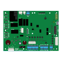
The MT2300 is the base unit controller for the Daikin Applied
water source heat pump control platform. The MT2300 controls
the heat pump in all modes of operation, including:
• Single State Compressor
• Single/Two-speed Fan (Induction or ECM)
• Loop Pump On/O
• Reversing Valve On/O
• Alarm (Dry Contacts)
• Network Integration (with a BACnet Communications
Module)
The controller can be used with thermostat or sensor control.
All MT2300 unit controller inputs must be activated by dry
contacts powered by the control board’s power terminals or
approved Daikin Applied sensors. No solid state devices (Triacs)
may be used to operate MT2300/MT2310 unit controller inputs.
No external power sources may be used to operate MT2300. All
units must be properly grounded per local code requirements.
See the Installation and Maintenance bulletin specic to your
Water Source Heat Pump.
Connecting a MT2310 expansion board to the main controller
allows:
• Compressor High Capacity On/O Control
• Variable Speed Fan Control
• Water Side Economizer Control
• Active Hot Gas/Reheat (HGR), or Low Capacity
Dehumidication Options
• Boilerless & Supplemental Auxiliary Heating Options
• The Third and Fourth Thermostat Heating Stage (W3 and
W4) Input
• Hydronic Heating Control
The I/O of the MT2300 unit controller can be extended to support
additional functions with the MT2310 expansion board.
Your Daikin water source heat pump will be delivered with
the correct unit controls installed to support the specic unit
conguration.
Operating Modes
• Occupied Mode – When in the occupied mode, the unit
will be controlled to its occupied setpoint conditions.
The occupancy mode can be established by a BACnet
communication signal, from a room sensor equipped with
“Occupied/Unoccupied” mode functions, or a thermostat
equipped with an “Occupied/Unoccupied” mode switch. The
occupancy state will be displayed on sensors equipped with
a status indicator.
• Unoccupied Mode – When in the unoccupied mode, the
unit will be controlled to its unoccupied setpoints. The
occupancy state will be displayed on sensors equipped with
a status indicator.
A contact closure between terminals U and C on the
MT2300 unit controller will place the unit into the
unoccupied mode for night setback/setup operation.
Thermostat equipped units will be controlled from Y2, W2,
W3, W4 and DH inputs. The fan will cycle according to a
call for cooling, heating, or dehumidication.
• Override Mode – A momentary (4 to 10 seconds) press
of the “Override” button on the thermostat or room sensor
during the unoccupied mode will cause the unit to operate
in the occupied mode for up to two hours, for after-hours
heating, cooling or dehumidication. “OVERRIDE” will be
displayed on sensors equipped with override button and
status indicator.
• “Energy Save” Standby – BACnet units congured for
Room Sensor Control can receive a signal from the Building
Automation System (BAS) to initiate the energy savings
mode. This mode is typically initiated by the BAS with smart
grid technologies to save energy. The savings are driven
by reducing peak electrical demand for the building. Once
initiated, the MT2300 SmartSource
®
unit controller will reset
its eective setpoint to minimize compressor operation.
“E-SAVE” will be displayed on sensors equipped with
bypass mode annunciation capabilities.
• Remote Shutdown – When the unit is in the remote
shutdown mode, unit operation is suspended. A contact
closure between terminals E and C on the MT2300 unit
controller will place the unit into remote shutdown mode.
Safety Inputs (HPS, LPS, SLTS, COS)
The control inputs are High Pressure Switch (HPS), Low
Pressure Switch (LPS), Suction Line Temperature Sensor
(SLTS), Condensate Overow Sensor (COS). These inputs are
active while the unit is in any occupancy mode. Protect unit
components by disrupting normal operation as follows:
• High Pressure Switch (HPS) – Normally closed switch
that opens on a high refrigerant pressure condition.
Control generates a high pressure fault and disables the
compressor output when the switch is open. High pressure
inputs are only valid when the compressor output relay is
energized.
• Low Pressure Switch (LPS) – Normally closed switch
that opens on a low refrigerant pressure condition. Control
generates a low pressure fault and disables the compressor
output when the switch is open.
• Suction Line Temperature Sensor (SLTS) – Monitors
refrigerant suction line temperature. When the suction
temperature drops below the cutout setpoint, the control
generates a low temperature fault and disables the
compressor output.
• Condensate Overow Sensor (COS) – Senses
condensate level in condensate pan. When the sensor
indicates a potential overow condition, the control
generates a condensate overow fault and disables the
compressor output. Condensate overow alarm is disabled
in the heating mode.