REPLACING UNIT CONTROLLER
MICROTECH 2300 UNIT CONTROLLERDAIKIN APPLIED
6
Replacing Unit Controller
1. Connect wrist strap to unit.
2. Remove faulty board and place on static protected surface.
3. Remove replacement unit controller from static protection
bag.
NOTICE
Hold circuit board by edges to avoid static damage of circuit board components.
4. Holding unit controller in grounded hand, install controller
in unit.
5. Insert faulty board in empty static bag for return.
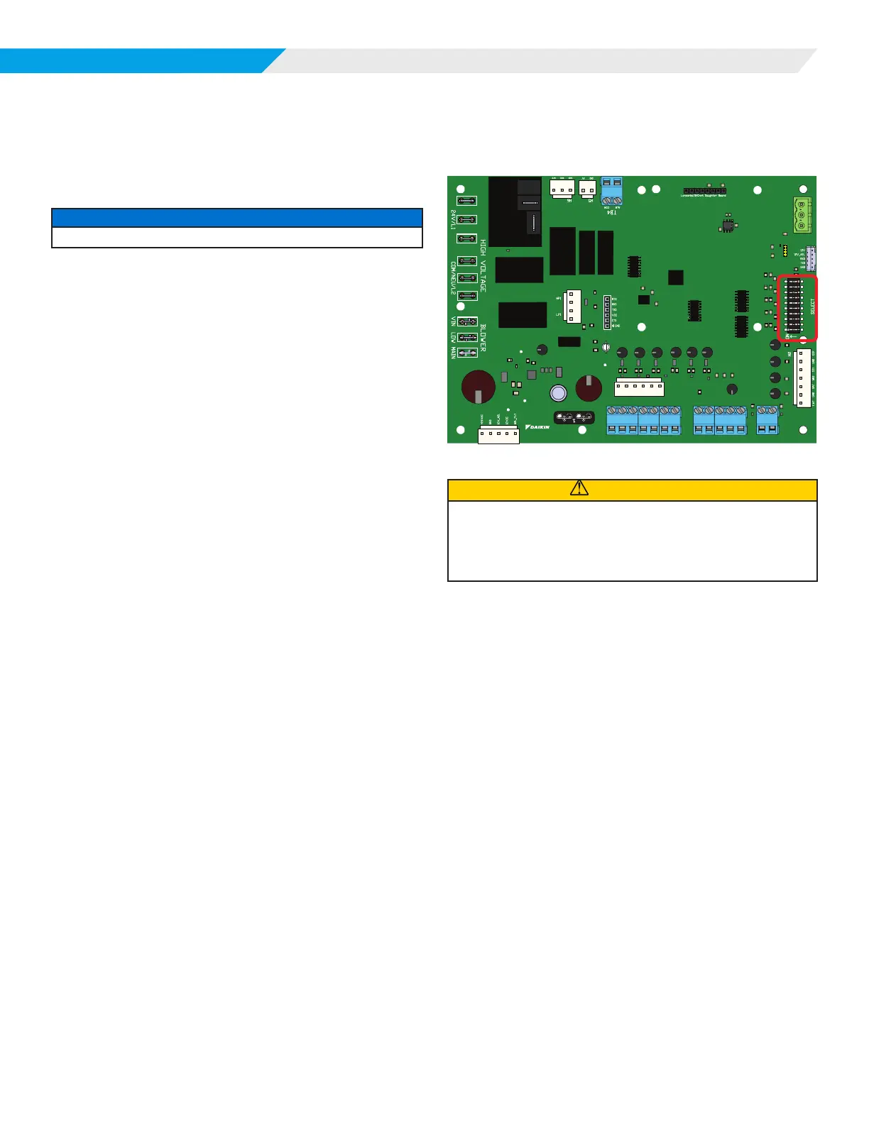
Conguration DIP Switches
Figure 2: Location of conguration DIP Switches on the
MT2300 Unit Controller
R
H7
H8
H1
LED
FM
SP
RM
GND
LED
FM
SP
RM
GND
TB3
TB2
TB1
E
E
U
U
W2
W1
Y2
Y1
G
C
R
W2
W1
Y2
Y1
G
C
MT2300
PART# 910384405
H3
10
9
8
7
6
5
4
3
2
1
H4
RY/FAN_HIGH
RY/FAN_EN
RY/PUMP
CAUTION
The MT2300 unit controller incorporates static sensitive devices. A static
charge from touching the device can damage the electronic components. To
help prevent damage during service, use static discharge wrist straps. Static
discharge wrist straps are grounded to the heat pump chassis through a 1M
ohm resistor.