1
3
456
7
8
9
10
2
11
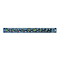
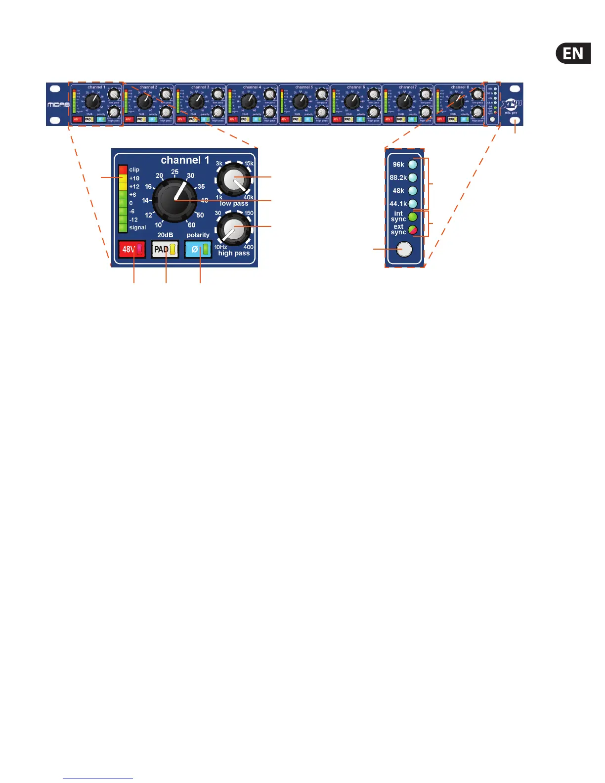
3. Front Panel
(1) low pass control knob — adjusts the low pass lter in the range
1kHzto40kHz.
(2) Gain control knob — adjusts the mic gain in the range +10 dB to +60 dB.
(3) high pass control knob — adjusts the high pass lter in the range
10Hzto400Hz.
(4) Ø button — this polarity button reverses the phase by 180°. The integral
green LED illuminates to show that this button is on.
(5) PAD button — this button reduces the mic signal by 20dB. The integral
yellow LED illuminates to show that this button is on.
(6) 48 V button — this phantom power button, when on, supplies +48 volts to
the mic. The integral red LED illuminates to show that this button is on.
(7) Meter — this 8-segment LED meter shows the signal level(dB).
(8) Sample frequency LEDs — one of these four blue LEDs will illuminate to
show which sample rate frequency (kHz) is currently selected, that is, 44.1 k,
48 k, 88.2 k or 96 k.
(9) Synchronisation (sync) source LEDs — either of these LEDs will illuminate to
show the current sync source (internal or external).
(10) Selection switch — use this switch to choose the sample frequency and
clock sync.
(11) There are four cut-outs for rack mounting xings.
 Loading...