Home
Middleby Marshall
Oven
PS360 SERIES
Middleby Marshall PS360 SERIES Technical & Service Manual
5
of 1
of 1 rating
182 pages
Give review
Manual
Specs
To Next Page
To Next Page
To Previous Page
To Previous Page
Loading...
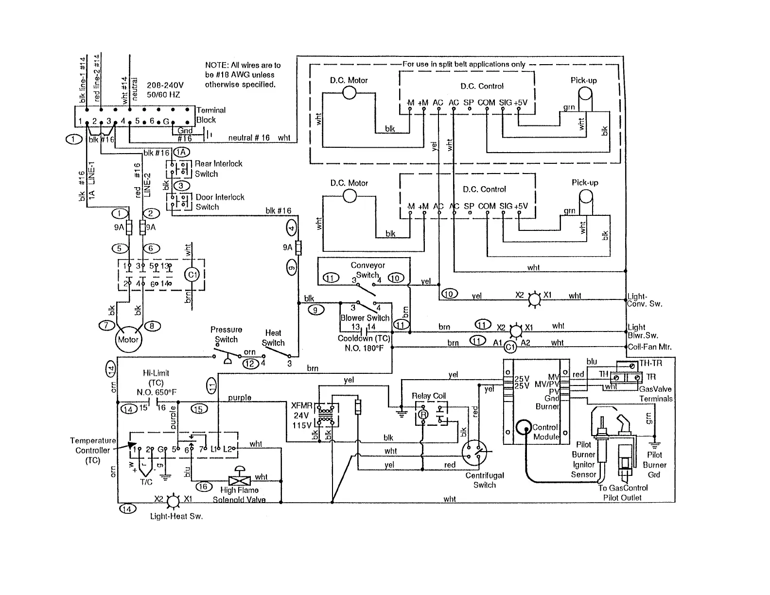
151
PS200-series
gas
oven
(with
solenoid valve
and
analog temp
control),
208/240V main
blower
motor
, 120V
control circuit
208/240V
, 50/60
Hz, 1
Ph,
3 pole,
4 wire
supply
(2 hot,
1 neutral,
1 ground)
SECTION
4
-
ELECTRICAL
WIRING
DIAGRAMS
I
I
.
PS200-SERIES
OVENS
151
153
Table of Contents
Notice Middleby Marshall Reserves the Right to Change Specifications at any Time.
3
Table of Contents
3
Section 1 - Sequence of Operation
5
Gas Oven Sequence of Operation
5
Electric Oven Sequence of Operation
7
Section 2 - Air Flow and Heat Transfer
8
Types of Heat Transfer
8
Blowers and Blower Speed
8
PS200-Series Ovens
8
PS360-Series Ovens
9
PS555/570-Series Ovens
9
Air Fingers
9
Description and Function
9
Configuration and Alignment
10
Performing a Test Bake
10
PS300/350 Air Finger Shutter Adjustment
11
Oven Capacity
13
Conveyor Speed and Bake Time
13
Belt Time
13
Time of Delivery (TOD)
13
Section 3 - Troubleshooting and Servicing Components I. Conveyor Speed Controller and Drive Motor
14
Part Number Reference - Speed Controllers
14
Part Number Reference - Pickup Assemblies
15
Preparing to Service the Speed Controller
15
Controller/Motor Failure
16
Basic Troubleshooting Flowcharts
17
X95; if the Conveyor Runs at Full Speed
17
X95; if the Conveyor will Not Run at All
18
Initial Troubleshooting
19
Conveyor Control Pickup Test
20
Conveyor Motor Test
20
Replacing the Magnetic Pickup
20
Unshielded Pickup Wires on Early PS360-Series Ovens . 19 K. Appendices
20
Conveyor Sensor Wiring Changes for PS360-Series and PS570S, 10/95
21
Service Bulletin MM-133B - Installation Instructions for Conveyor Speed Controller Kit with Thumbwheel, P/N 42810-0133, 4/95
22
Speed Controller Kit with Thumbwheel, 4/95
24
Service Bulletin MM-177 - Introduction and Compat- Ibility of Conveyor Speed Controller with Digital Display, P/N 37337, 8/00
28
Instructions for Service Kit 44756 - Conveyor Speed Controller Kit for PS200R68-Series Ovens, 2/02
29
Service Bulletin MM-189 - New Conveyor Gear Motors, Brushes, and Pickup Clamps, 8/01
30
With Digital Display (P/N 37337), 4/02
31
Temperature Controller
31
Part Number Reference - Temperature Controllers
32
Description
33
High Limit/Cooldown Functions
33
Troubleshooting
33
Appendices
33
E. Appendice S
33
Temperature Controller Terminal Cross-Reference, 4/02
33
Instructions for Service Kit 47321 Digital Temperature Controller
34
Temperature Controller Kit, 2/02
34
Appendix - Instructions for Service Kit 47321 - Digital Temperature Controller Kit, 2/02
35
Controller Types
35
Before You Begin
36
Installation
36
Electrical Connections
37
Jumper Setting
39
Programming
39
Diagnostic Error Messages
41
Operating Instructions (to be Left with Customer after Installation)
42
741-3300 • FAX (847) 741-4406
43
High Limit Control Module
46
Part Number Reference - High Limit Control Modules
46
Location
46
Troubleshooting
46
Appendices
47
Instructions for Service Kit 39733 - High Limit Conversion Kit for PS300, 310, 350 & 360 Ovens, 5/99
47
Thermocouples
55
Part Number Reference - Thermocouples
55
Thermocouple Functions
55
Troubleshooting
55
Instructions for Service Kits P/Ns 33984 and 33985 Oven Thermocouple Kit
57
Appendices
57
Oven Thermocouple Kit, 11/01
57
Appendix - Instructions for Service Kits 33984 and 33985 -
58
PS200 Series - 2/96 or Later, Serial Numbers after ASH-0001
58
PS200 Series - before 2/96, Serial Numbers before ASH-0001
58
PS360 Series Rear Wall Thermocouples - before 2/96, Serial Numbers before ASH-0001
59
Machinery Compartment
60
Ps536
61
PS555 Electric and PS555E
63
PS570 (X01-X05 Name Plate ID Numbers) and PS570S (Early) with Side-Mounted Thermocouples Inside or Outside the Blower Motor Compartments
64
PS570S (Late) - Rear Wall Thermocouples with Left-Side and Right-Side Terminal Block Connections
66
PS555G and PS570G Rear Wall Thermocouples with Left-Side Terminal Block Connections
68
Blowers
69
PS200-Series Ovens
69
PS360-Series Ovens
75
PS555/570-Series Ovens
77
Blower Motor Centrifugal Safety Switch (PS360-Series)
81
Part Number Reference - Blower Centrifugal Switch
81
Troubleshooting
81
Burner Blower Motor Centrifugal Safety Switch (PS200- Series Gas, PS310, PS314, PS360, PS360WB, PS570S)
81
Air Pressure Safety Switch (PS200-Series, PS555/570- Series, PS360EWB, PS360WB70)
82
Part Number Reference - Air Switches
82
Troubleshooting
83
Appendices
84
Air Pressure Switch Replacement Kits, 1/97
84
P/N 36194 with Service Kit P/N 35624, 3/97
86
PS570/570S Flame Gate
88
Part Number Reference - Flame Gate
88
Flame Gate Orientation
88
Gas Train and Burner System
89
Part Number Reference - Gas Train Components
89
Part Number Reference - Gas Orifices and Gas Conversion Kits
92
Component Identification
93
Pilot/Ignitor Assembly
94
Burner Blower Motor
96
Air Shutter
96
Burner Transformer
97
Burner Motor Relay
97
High Flame Solenoid Valve
97
Bypass (Low Flame) Orifice
97
Modulating Gas Valve
98
Amplifier Board
98
Combination Gas Control Valve
99
Ignition Module
100
Gas Conversion Kits
101
Burner and Gas Train Troubleshooting
101
Checking the Gas Pressures
103
Troubleshooting Flowcharts
104
X95; Intermittent Pilot System Troubleshooting Table
104
X95; no Spark, System Does Not Work
105
X95; Spark Is Present, Pilot will Not Light
106
X95; Pilot Lights, Main Valve will Not Come on
107
Appendices
108
Pilot/Ignitor Kit, 7/91
108
X95; Instructions for Service Kit 30185 - Pilot Tee
109
Combination Gas Valve, 1/92
113
Ignition Module, 11/90
117
During Burner Operation, 4/02
119
For Ovens with Wayne Burner, Natural Gas to
120
Propane, 8/00
120
For Ovens with Wayne Burner, Propane to
126
Natural Gas, 8/00
126
Instructions for Service Kit 36856 - Gas Conversion Kit for PS360EWB/WB70 with Midco Burner, Natural Gas to Propane, 1/98
132
Instructions for Service Kit 36863 - Gas Conversion Kit for PS360EWB/WB70 with Midco Burner, Propane to Natural Gas, 1/98
136
Equivalent Orifice Sizes at High Altitudes
140
Electric Oven Heating System
141
PS200-Series Ovens
141
PS310/360-Series Ovens
143
PS555 Ovens
145
Electric Oven Mercury Contactor Replacement
147
Component Wiring
150
Temperature Controllers
150
Ignition Modules
151
Section 4 - Electrical Wiring Diagrams
150
PS200-Series Ovens
152
PS310/360-Series Ovens
161
PS555/570-Series Ovens
167
Section 5 - Reference
173
25-Point Preventative Maintenance Checklist
173
Fractional Inches to Decimal and Millimeter Equivalents
174
Decimal Equivalents of Drill Sizes
174
General Conversion Factors
175
Pressure Conversions
175
Pressure Conversion Chart
176
Ohm’S Law Equation Wheel
176
Common Electrical Wiring Diagram Symbols
177
Other manuals for Middleby Marshall PS360 SERIES
Owner's Operating & Installation Manual
32 pages
Owner's Operating And Installation Manual
4 pages
5
Based on 1 rating
Ask a question
Give review
Questions and Answers:
Need help?
Do you have a question about the Middleby Marshall PS360 SERIES and is the answer not in the manual?
Ask a question
Middleby Marshall PS360 SERIES Specifications
General
Brand
Middleby Marshall
Model
PS360 SERIES
Category
Oven
Language
English
Related product manuals
Middleby Marshall PS360
182 pages
Middleby Marshall PS360GWB Gas
42 pages
Middleby Marshall PS314
24 pages
Middleby Marshall PS200
144 pages
Middleby Marshall PS520E
40 pages
Middleby Marshall PS740G
36 pages
Middleby Marshall PS740E
36 pages
Middleby Marshall PS570S
22 pages
Middleby Marshall PS555 series
182 pages
Middleby Marshall PS638 Series
51 pages
Middleby Marshall PS500 Series
72 pages
Middleby Marshall PS540G SERIES
40 pages
 Loading...