21
Use
3 USE
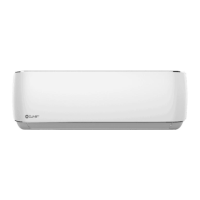
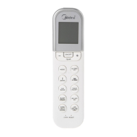
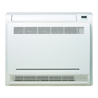
3.1 Description of system components
6
7
1
A
B
5
4
2
3
Fig. 19
A Air inlet
B Air outlet
1 Indoor unit
2 Ventilation louver
3 Filter
4 Remote control
5 Remote control support
6 Display led CRISTALLO
7 Display led ESSENTIAL 2
l
WARNING
The images in this manual are provided for
illustrative purposes only. The appearance
of your device may dier slightly from the
illustrations shown here. Refer to the actual
characteristics of the unit.
3.2 Meaning of the display codes
Icon Illustration
It displays for 3 seconds when:
• you set the start-up timer (TIMER ON)
• SWING, TURBO or SILENCE functions
are activated
It displays for 3 seconds when:
• you set the start-up timer (TIMER OFF)
• SWING, TURBO or SILENCE functions are
deactivated
When the function against cold air is
activated
When the defrost function is active
When the self-cleaning function of the unit is
in progress
When the frost protection is activated
When activating the WiFi Control function
When the ECO function is activated
It lights up in dierent colours depending on
the operating mode (some units):
• In cooling (COOL) or dehumidification (DRY)
mode, the symbol appears in a cold colour.
• In heating mode (HEAT), the symbol
appears in a warm colour.
NOTE: In ventilation mode (FAN), the unit shows room
temperature. In other modes, the unit shows the set
temperature.
 Loading...