Do you have a question about the Midea COMBI Series and is the answer not in the manual?
Provides essential safety instructions for operating the appliance and highlights potential hazards.
Details safety precautions related to the refrigerant, emphasizing handling and disposal risks.
Instructions on how to safely move and handle the refrigerator during transport, including post-move waiting periods.
Guidance on dismantling and reassembling the refrigerator doors, necessary if the unit doesn't fit through doorways.
Criteria for selecting an optimal installation location to ensure proper ventilation and energy efficiency.
Instructions on how to ensure the refrigerator is stable by adjusting its footing for proper leveling.
Steps for changing the door swing direction from left to right or vice versa.
Information regarding the installation of the door handle, noted as not applicable for this model.
Information regarding the installation of a door lock, noted as not applicable for this model.
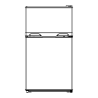
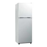
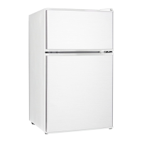
Identifies and labels the primary components of the refrigerator and freezer sections.
Provides detailed measurements and dimensions of the refrigerator's exterior and door opening requirements.
Illustrates the locations where the Serial Number (S/N) can be found on the product and its packaging.
Details electrical specifications including refrigerant type, compressor, power, and wiring resistance.
Specifies the temperature ranges for the freezing and refrigerating compartments.
Lists electronic components related to the defrosting system, such as sensors and fuses.
Presents a schematic diagram of the refrigerator's electrical and control circuits.
Visual representation of the main control board's layout and component placement.
Diagram and description of the refrigeration circuit, detailing the flow of refrigerant through various components.
Highlights specific locations or techniques required for soldering during repair or assembly.
Illustrates the airflow path within the refrigerator and freezer compartments for efficient cooling.
Instructions for removing components located on the refrigerator doors, such as seals and trays.
Guidance on how to remove internal parts like fruit box covers and shelves.
Procedures for accessing and replacing lighting components within the refrigerator and freezer.
Steps for dismantling air duct components and the fan motor in the refrigerating chamber.
Instructions for removing air duct components and fan motor from the freezing chamber.
Details on how to remove and service the evaporator and associated defrost system components.
Procedures for accessing and working with the compressor, including rear cover and pipe connections.
Indicates that there is no specific display control board section detailed for this model.
Instructions on how to access and remove the main control board (PCB) for maintenance or replacement.
Identifies the locations of the four temperature sensors within the refrigerator and freezing chambers.
Provides guidance on how to remove and replace sensors located in the refrigerating chamber.
General guidelines and steps for replacing temperature sensors, including cutting and connecting wires.
A table detailing the resistance (R) values of sensors at various temperatures (T) for diagnostic purposes.
Overview of the refrigerator's control panel, including button functions and display indicators.
Explanation of the display screen's behavior during power-on, normal operation, and fault conditions.
Instructions on how to adjust the temperature settings for both the refrigerator and freezer compartments.
Details on the door alarm function, including activation conditions and buzzer alerts.
Information on entering and exiting specific operational modes like 'Quick cool mode'.
A table listing fault codes (LED flickering patterns) and corresponding maintenance or troubleshooting steps.
Explanation of how the defrosting cycle operates in both freezing and refrigerating chambers.
Procedures for entering and operating the refrigerator in forced cooling and forced defrosting test modes.
Information on how the refrigerator's running state is remembered after power interruptions or settings changes.
Defines the conditions under which the compressor will start or stop, based on temperature and runtime.
Troubleshooting flowchart for diagnosing and resolving issues related to the refrigerator and freezer not cooling.
Diagnostic steps to identify why the compressor is not operating, checking power, PCB, and accessories.
Troubleshooting guide for frost build-up inside the unit without proper defrosting, examining door seals and air ducts.
Detailed maintenance guidelines for addressing internal frosting issues, covering door seals, air ducts, and sensors.
Troubleshooting steps for when the internal lights of the refrigerator are not functioning.
Diagnostic procedures for identifying and resolving issues related to fan operation or failure.
Steps to identify and resolve problems with the defrost circuit, including checking fuses, timers, and wiring.
Guidance on identifying the source of unusual noises within the refrigerator and potential solutions.
Troubleshooting steps for when the air duct system is not functioning electronically, often related to airflow or noise.
Instructions for accessing the Midea TSP system, including website links and login credentials.
| Brand | Midea |
|---|---|
| Model | COMBI Series |
| Category | Refrigerator |
| Language | English |