12 32808001101
Specifications subject to change without notice.
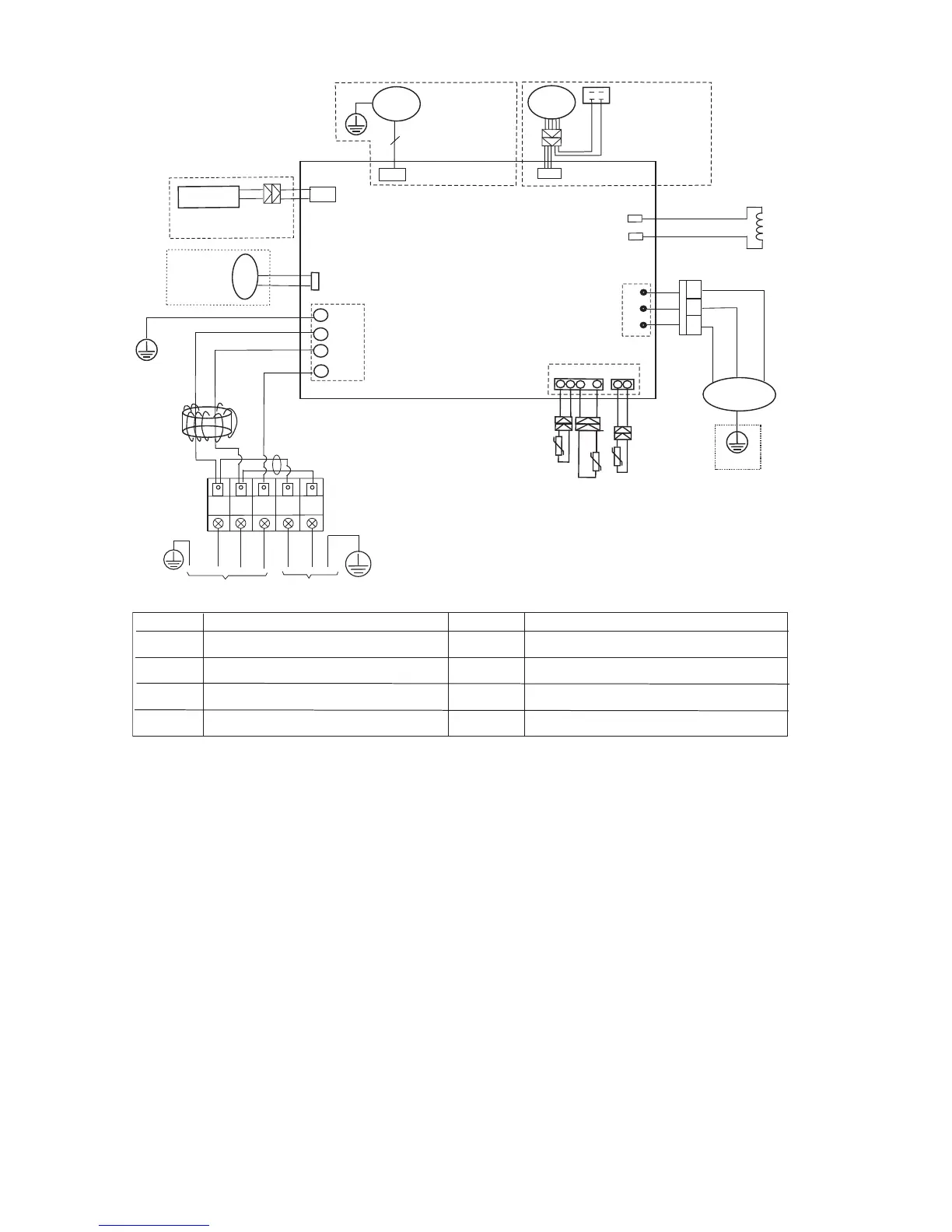
WIRING DIAGRAMS (CONTINUED)
1
2
3
U
V
W
CN60
COMPRESSOR
Y/G
RED
BLUE
B
LACK
OUTDOOR
MAIN
PCB
BLUE
BL
ACK
RED
CN13
CN12
W-
4AY
REACTOR
BLUE
BLUE
U
V
W
Y/G
RED
L1
L2
S
L1
L2
72,1'22581,7
32:(56833/<
BLACK(BLUE)
L1
L2
OPTIONAL˖
CN16
OPTIONAL:the electric
heating belt of compressor
HEATER 1
OUTDOOR WIRING DIAGRAM
OUT DOOR
DC FAN
CN414
3
OUT DOOR
AC FAN
F
N
A
PACTICARO
BROWN
BLUE
CN5
Applicable to
the units adopting
DC motor only
Applicable to
the units adopting
AC motor only
Y/G
CN30
CN10
CN1
CONDENSER
TEMPERATURE SENSOR
OUTDOOR AMBIENT
TEMPERATURE SENSOR
WHITE
BLAC
K
DISCHARGE SENSOR
KCALB
DER
CN17
(RED)
BLACK
(BLACK)
CN2
CN7
CN8
Y/G
CN6-1
NWOR
B
BLUE
δYELLOWε
CN3
&2'(
&1
&1
&1
&2'(
&1
&1
&1
3$571$0( 3$571$0(
Input: 230V high voltage connector with
L1/L2/signal/ground
Output: 0~320VDC to control DC FAN
Output: PWM for UVW to control
Compressor(0~320VAC)
Output: 220V AC to control crankcase heater
Output: 0~220V AC to control 4-way valve
Input: Temperature acquisition(0-5VDC)
&1
Output: 0~220VAC to control AC FAN
CN12/CN13
Output: Connection of the high voltage
(REACTOR)
Fig. 9 - Wiring Diagram Sizes 18K − 24K (Heat Pump Units)
 Loading...