Page 7
4.5 Electric Connection
Remove the electrical compartment cover on the right hand side
and connect the wires accordingly.
(Where possible terminate the electrical connection with a suitable
isolating switch (By authorised electrician)
• The power supply should be hard wired.
• Power supply circuit should be earthed effectively. The wiring
must be performed by professional technicians in accordance
with national wiring regulations and the circuit diagram.
• An all-pole disconnection device which has at least 3mm
separation distance in all pole and a residual current device
(RCD) with the rating of above 10mA shall be incorporated in
the fixed wiring according to the national rule.
• Set the electric leakage protector according to the relevant
electric technical standards of local regulations.
• All electrical works shall be properly run using suitable conduit
/ insulation without contacting any of the piping or valves.
• The power cord and the signal cord shall be laid out neatly
and properly without mutual interference or contact the
connection pipe or valve.
• After wire connection, check it again and make sure of
connection before power is turned on.
WARNING
The unit must be installed with an RCD near the power supply
and must be effectively earthed.
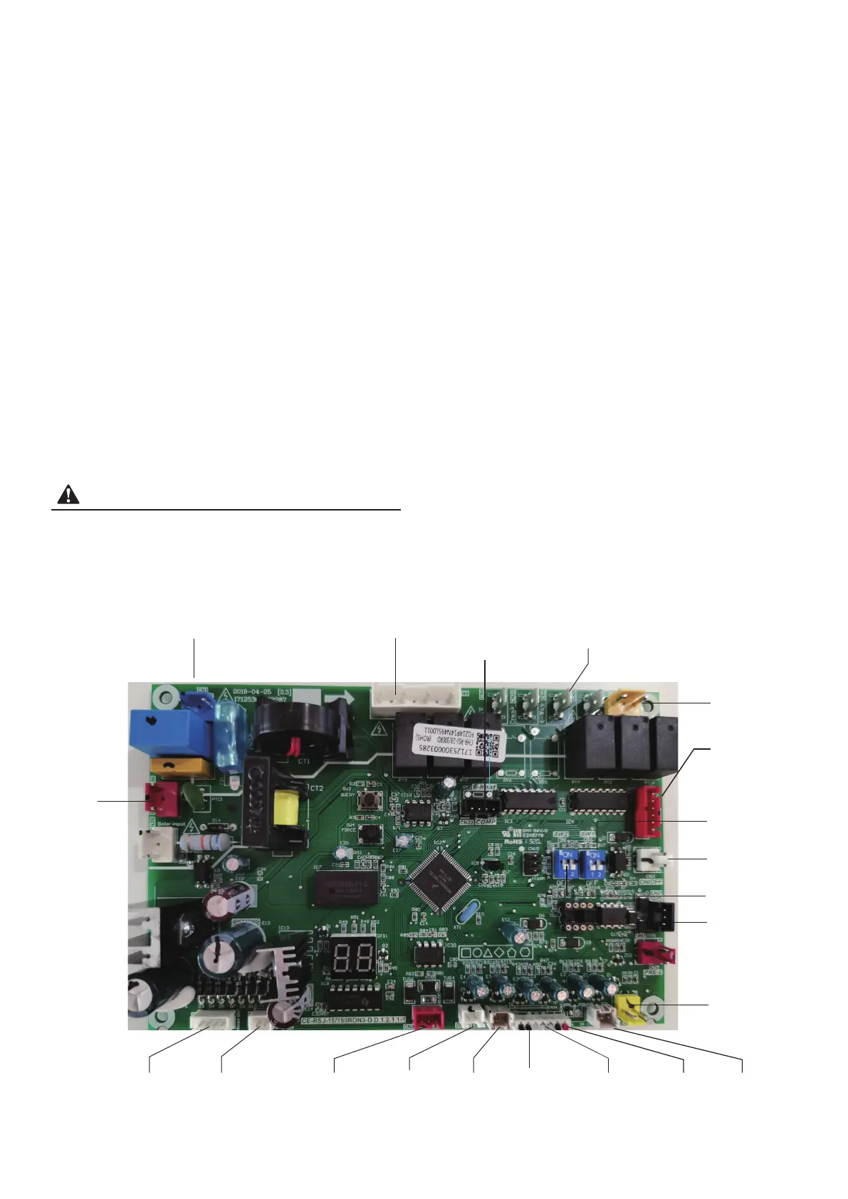
3.2.3 PCB I/O Ports description
Fig.3-4
Alarm
SW1 Factory Setting
for Disinfect
&Electric Heater
Model Selection
SW2 Factory Setting
for 190L/300L Model
Selection
High Pressure
Switch
Tp:Comp
Discharge
Temp.Sensor
Transformer
Output
Transformer
Input
Power Supply
Fan
To Comp. Relay
& E-heater Relay
4-way
Valve
Panel Display
Power Supply
Output
Panel Display
Output
T5L:Lower
Tank Water
Temp.Sensor
T5U:Upper
Tank Water
Temp.Sensor
T4:Ambient
Temp.Sensor
T3:Evaporator
Inlet Temp.
Sensor
Th:Comp
Suction
Temp.Sensor
EEV
ON/OFF
To computer
4.5.2 PCB I/O Ports Description