25
When a safety device is activated, an error code will be displayed on the user interface.
A list of all errors and corrective actions can be found in the table below.
Reset the safety by turning the unit OFF and back ON.
In case this procedure for resetting the safety is not successful, contact your local dealer.
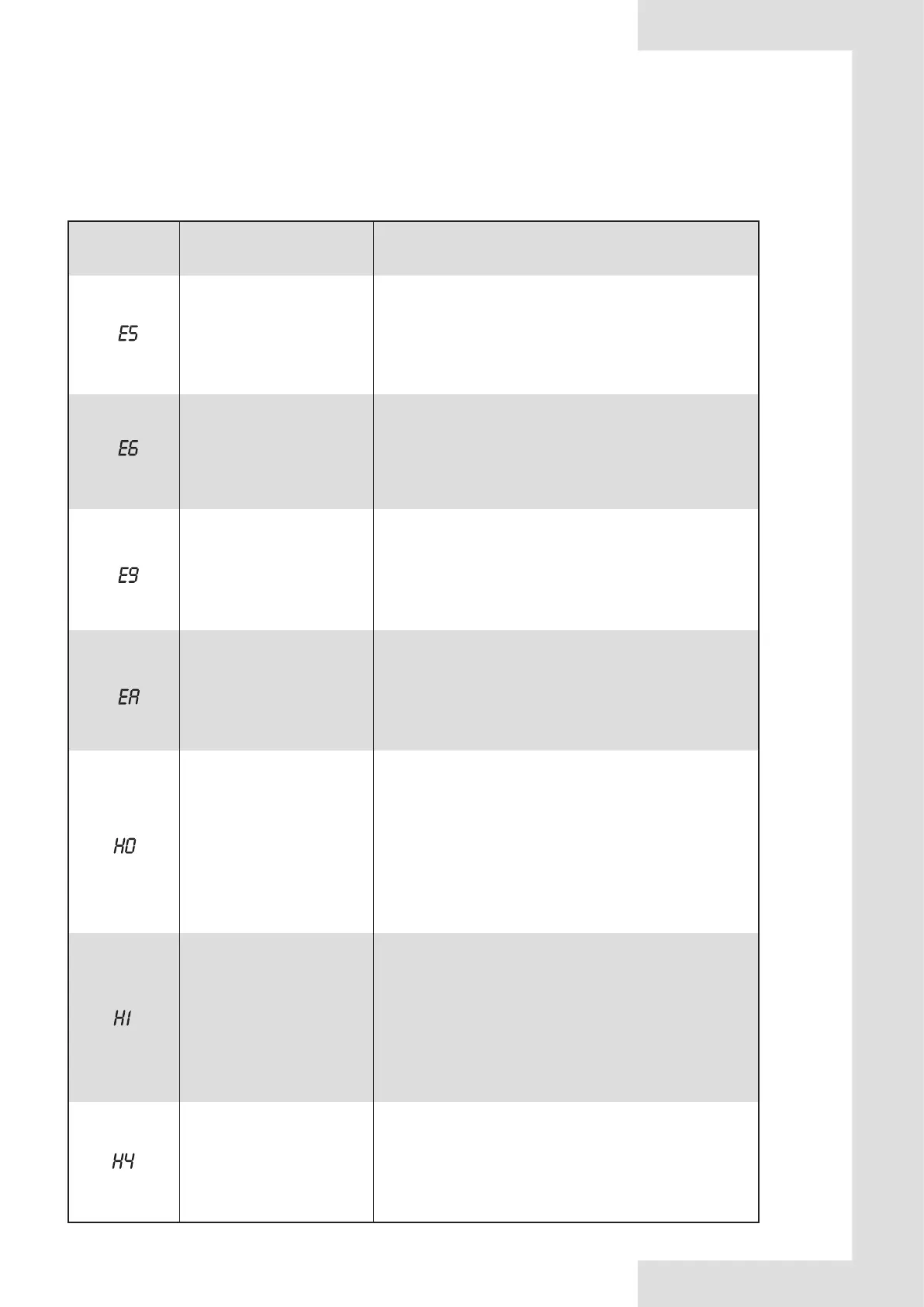
13.8 Error codes
ERROR
CODE
MALFUNCTION
OR PROTECTION
FAILURE CAUSE
AND CORRECTIVE ACTION
1. The T3 sensor connector is loosen. Reconnect it.
2.The T3 sensor connector is wet or there is water in. remove
the water, make the connector dry. Add waterproof adhesive
3. The T3 sensor failure, change a new sensor.
The condenser outlet
refrigerant temperature sensor
(T3)error.
1. The T4 sensor connector is loosen. Reconnect it.
2.The T4 sensor connector is wet or there is water in. remove
the water, make the connector dry. Add waterproof adhesive
3. The T4 sensor failure, change a new sensor.
The ambient temperature
sensor (T4) error.
1. The Th sensor connector is loosen. Re connect it.
2.The Th sensor connector is wet or there is water in. remove
the water, make the connector dry. Add waterproof adhesive
3. The Th sensor failure, change a new sensor.
Suction temperature
sensor(Th) error
1.wire doesn’t connect between main control board PCB B and
main control board of hydraulic module. connect the wire.
2.Communication wire sequence is not right. Reconnect the
wire in the right sequence.
3. Whether there is a high magnetic field or high power
interfere, such as lifts, large power transformers, etc.. To add a
barrier to protect the unit or to move the unit to the other place.
Communication error between
main control board PCB B and
main control board of
hydraulic module
1. The Tp sensor connector is loosen. Re connect it.
2.The Tp sensor connector is wet or there is water in. remove
the water, make the connector dry. Add waterproof adhesive
3. The Tp sensor failure, change a new sensor.
Discharge temperature
sensor(Tp) error
1. Whether there is power connected to the PCB and driven
board. Check the PCB indicator light is on or off. If Light is off,
reconnect the power supply wire.
2.if light is on, check the wire connection between the main
PCB and driven PCB, if the wire loosen or broken, reconnect
the wire or change a new wire.
3. Replace a new main PCB and driven board in turn.
Communication error between
inverter module PCB A and
main control board PCB B
Same to P6
Three times P6 protect
 Loading...