EasyManua.ls Logo

Midea M2OC-18HRDN1-M User Manual

Midea M2OC-18HRDN1-M
39 pages
To Next Page IconTo Next Page
Page #1 background imageLoading...
Page #1 background image
ODMI-A-1110
SERVICE MANUAL
MIDEA AIRCONDITIONER
North America MARKET
DC INVERTER MULTI TYPE
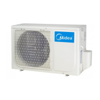
M2OC-18HRDN1-M
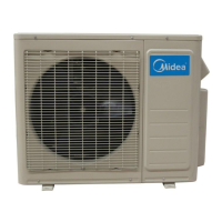
M3OC-27HRDN1-M
M4OC-36HRDN1-M
DC MULTI OUTDOOR UNITS

Questions and Answers:

Midea M2OC-18HRDN1-M Specifications

General IconGeneral
BrandMidea
ModelM2OC-18HRDN1-M
CategoryAir Conditioner
LanguageEnglish

Summary

General Information of Outdoor Units

Features

Dimensions

Wiring Diagram

4.1 M2OC-18HRDN1-M

Wiring diagram for M2OC-18HRDN1-M outdoor unit.

4.2 M3OC-27HRDN1-M

Wiring diagram for M3OC-27HRDN1-M outdoor unit.

4.3 M4OC-36HRDN1-M

Wiring diagram for M4OC-36HRDN1-M outdoor unit.

Refrigeration Cycle Diagram

5.1 Refrigeration circuit drawing of inverter dual zone

Refrigeration circuit for dual zone inverter systems.

5.2 Refrigeration circuit drawing of inverter tri-zone

Refrigeration circuit for tri-zone inverter systems.

5.3 Refrigeration circuit drawing of inverter qua-zone

Refrigeration circuit for quad-zone inverter systems.

Indoor units combination

6.1 Indoor unit combination for M2OC-18HRDN1-M

Indoor unit combinations for M2OC-18HRDN1-M model.

6.2 Indoor unit combination for M3OC-27HRDN1-M

Indoor unit combinations for M3OC-27HRDN1-M model.

6.3 Indoor unit combination for M4OC-36HRDN1-M

Indoor unit combinations for M4OC-36HRDN1-M model.

Installation Details

7.1 Wrench torque sheet for installation

Torque specifications for installation fasteners.

7.2 Connecting the cables

Guidelines for selecting and connecting power and communication cables.

7.3 Pipe length and the elevation

Specifications for pipe length, elevation, and refrigerant charge.

7.4 Installation for the first time

Procedures for initial system installation and evacuation.

7.5 Adding the refrigerant after running the system for many years

Procedure for adding refrigerant to older systems.

7.6 Re-installation while the indoor unit need to be repaired

Steps for refrigerant collection before indoor unit repair.

7.7 Re-installation while the outdoor unit need to be repaired

Steps for system evacuation during outdoor unit repair.

Electronic control function

8.1 Abbreviation

List of abbreviations for temperature and sensor readings.

8.2 Electric control working environment.

Specifications for input voltage, frequency, and operating currents.

8.3 Outdoor unit's digital display tube

Explanation of the outdoor unit's digital display functions.

8.4 Outdoor unit point check function

Procedure for checking unit states via a switch and display.

8.5 Protection

Details on various protection mechanisms for the unit.

Troubleshooting

9.1 Indoor unit error code explanation:

Explains error codes displayed on indoor units.

9.2 Outdoor unit error code explanation:

Explains error codes displayed on outdoor units.

9.3 Trouble shooting

General guidance for troubleshooting issues.

9.3.2 Outdoor unit trouble shooting

Specific troubleshooting steps for outdoor unit issues.

Annex 1

Characteristic of temp. sensor

Table of temperature sensor resistance values at different temperatures.

Annex 2

Reference voltage data:

Lists reference voltage data for rectifier and inverter modules.

Related product manuals