Installation
Page 124
6. Feed the signal wire through this slot, from the back of
the unit to the front.
7. Facing the front of the unit, match the wire colors with
the labels on the terminal block, connect the u-lug and
and firmly screw each wire to its corresponding terminal.
8. After checking to make sure every connection is secure,
use the cable clamp to fasten the signal cable to the unit.
Screw the cable clamp down tightly.
9. Replace the wire cover on the front of the unit, and the
plastic panel on the back.
For All Easy series:
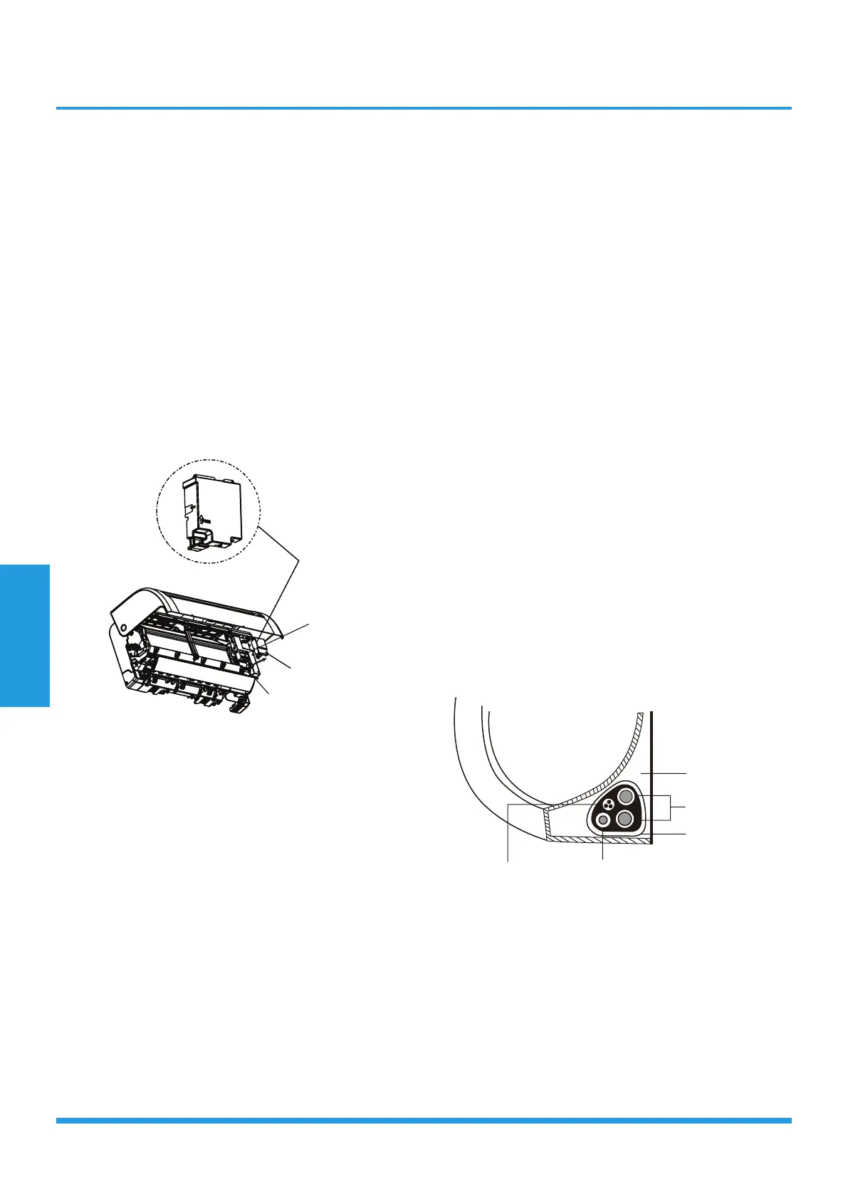
1. Open front panel of the indoor unit by loosen the
screws according to picture below, which provide big
space for wiring connection.
2. Open the wire box cover to connect the cable.
block
Wire
cover
Cable
3.Unscrew the cable clamp below the terminal block and
place it to the side.
4.Facing the back of the unit, remove the plastic panel on
the bottom left-hand side.
5. Feed the signal wire through this slot, from the back of
the unit to the front.
6. Facing the front of the unit, connect the wire according
to the indoor unit’s wiring diagram, connect the u-lug and
firmly screw each wire to its corresponding terminal.
7. After checking to make sure every connection is secure,
use the cable clamp to fasten the signal cable to the unit.
Screw the cable clamp down tightly.
8. Replace the wire cover on the front of the unit, and the
plastic panel on the back.
NOTE:
• Choose the right cable size
The size of the power supply cable, signal cable, fuse, and
switch needed is determined by the maximum current
of the unit. The maximum current is indicated on the
nameplate located on the side panel of the unit. Refer to
this nameplate to choose the right cable, fuse, or switch.
• Take note of fuse specifications
The air conditioner’s circuit board (PCB) is designed with a
fuse to provide overcurrent protection. The specifications
of the fuse are printed on the circuit board, such as: Indoor
unit: T5A/250VAC, etc.(The fuse is made of ceramic.)
• Pay attention to live wire
While crimping wires, make sure you clearly distinguish the
Live (“L”) Wire from other wires.
• All wiring must performed strictly in accordance with
the wiring diagram located on the inside of the indoor
unit’s wire cover.
• Do not mix up live and null wires.
This is dangerous, and can cause the air conditioning unit
to malfunction.
• The wiring connection process may differ slightly
between units.
3.7 Wrap piping and cables
Before passing the piping, drain hose, and the signal cable
through the wall hole, you must bundle them together to
save space, protect them, and insulate them.
1. Bundle the drain hose, refrigerant pipes, and signal
cable according to the picture below:
Indoor Unit
Space behind unit
Refrigerant piping
Drain hose
Signal wire
Insulation tape
2. Using adhesive vinyl tape, attach the drain hose to the
underside of the refrigerant pipes.
3. Using insulation tape, wrap the signal wire, refrigerant
pipes, and drain hose tightly together. Double-check that
all items are bundled in accordance with the picture above.
NOTE:
• Drain hose must be on bottom
Make sure that the drain hose is at the bottom of the
bundle. Putting the drain hose at the top of the bundle
can cause the drain pan to overflow, which can lead to fire
or water damage.
 Loading...