Index 1:
1. DC Fan Motor (control chip is in PCB)
Release the UVW connector. Measure the resistance of U-V, U-W, and V-W. If the resistances are not
equal to each other, the fan motor may be experiencing problems and need to be replaced. Otherwise,
the PCB must has problems and need to be replaced.
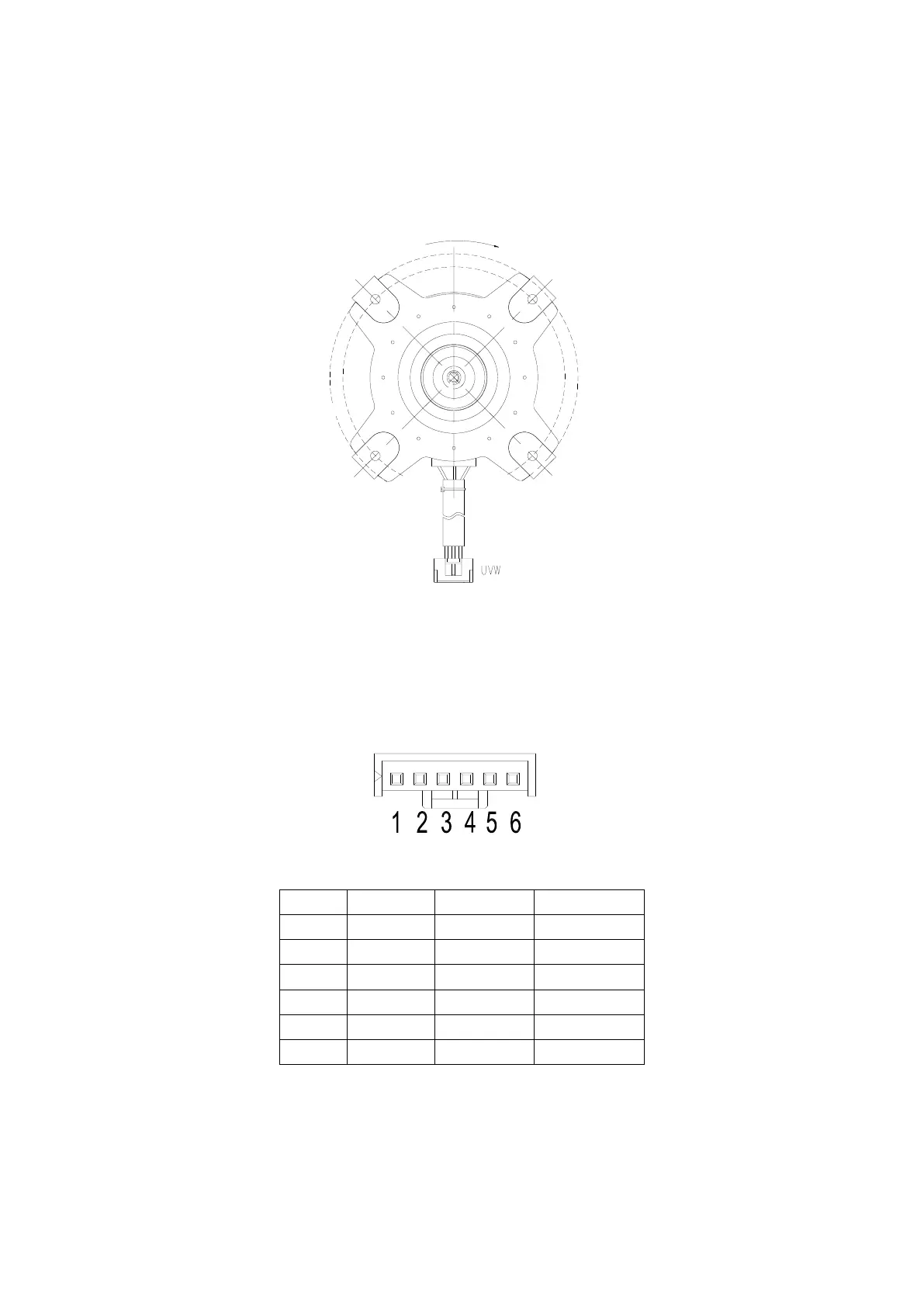
2. DC fan motor (Control Chip is in Fan Motor)
Turn power on and while the unit is on standby, measure the voltage between pin1 and pin3 as well as
between pin4 and pin3 in fan motor connector. If the value of the voltage is not within the range shown
in the following table, the PCB may be experiencing problems and need to be replaced.
DC motor voltage input and output
3. DC Fan Motor(for some double fan models)
Power on and when the unit is in standby, measure the voltage of CON1, pin1-pin2 and
pin3-pin2 of CN1 in DC motor driver board. If the value of the voltage is not in the range
 Loading...