6. ELECTRIC WIRE DIAGRAM
MHC-96HWD1N1
(
A
)
This wire diagram is applicable to both cooling and heating model.
9
Table.5-1
Indoor unit Outdoor unit
MHC-96HWD1N1
(
A
)
220-240V~ 50Hz
380-415V 3N~ 50Hz
Model
Power
Switch capacity of the main
power suppliy/fuse(A)
Indoor unit power cable(mm
2
)
includes grounded wire
Outdoor unit power cable(mm
2
)
includes grounded wire
16/16 40/40
3×2.5 mm
2
MOUA-96HD1N1-R
5×6.0 mm
2
Indoor Unit /Outdoor
Unit Signal Wire (mm
2
)
(Weak electric signal)
3-core shielded wire
3X0.75
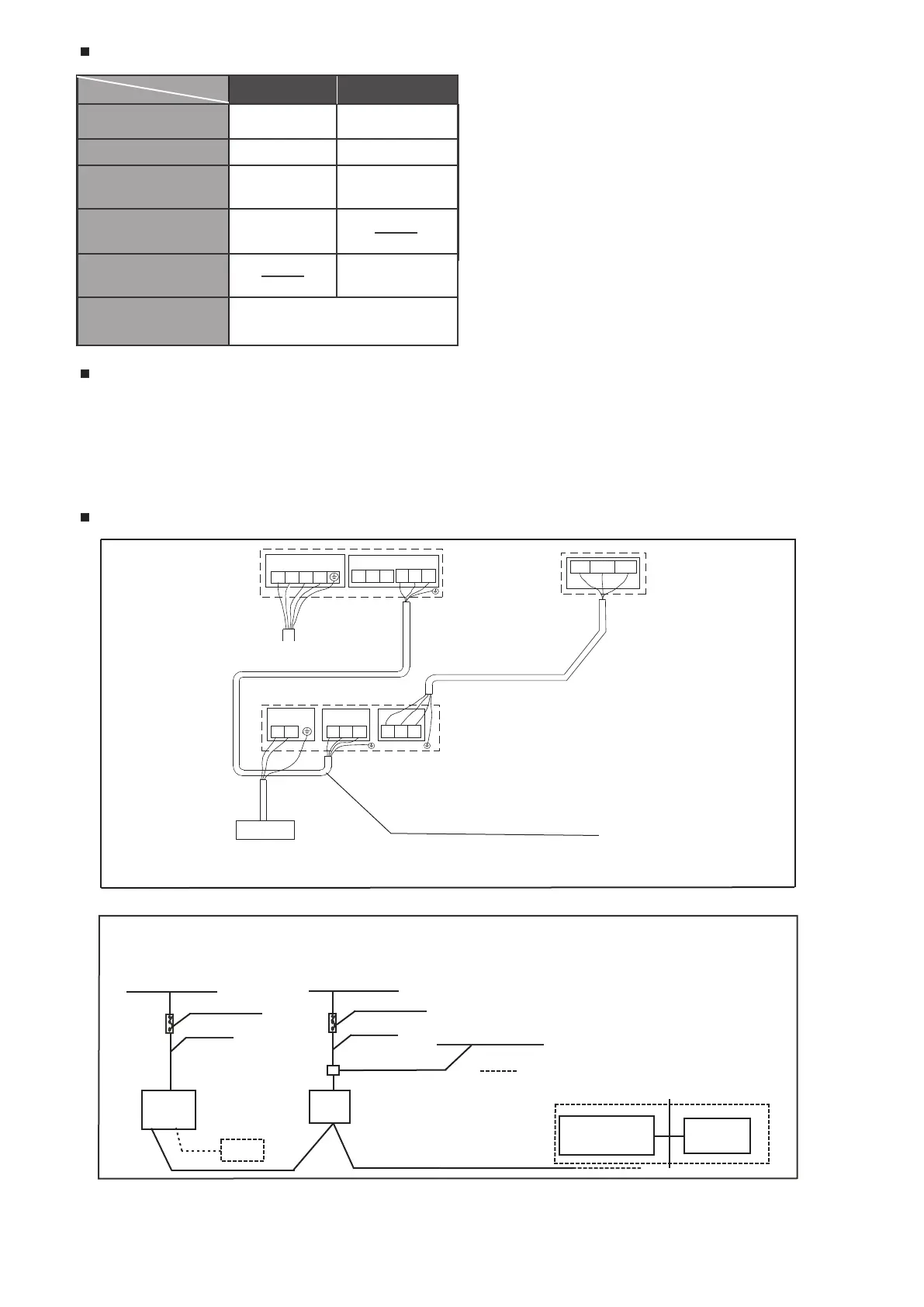
Fig. 6-1
Outdoor unit
Signal wire between indoor/outdoor unit
Indoor unit
N
L1 L2 L3
P Q E
L
N EQP EYX
Y EX
CCM
Branch Box
Please use 3-core shielded wire, and
connect the shielded layer to Grounding
Power Supply
Power Supply
X Y E
Fig. 6-2
Outdoor
Unit
Indoor
Unit
Power wiring
(indoor)
Communication Bus
wire distribution box
Switch / Circuit breaker
Switch / Circuit breaker
Power wiring
(outdoor)
Central control
monitor (CCM)
CCM
Computer
in broken line table, users can purchase the Central
control montior when necessary.please contract
with local supplier in details .
Power (380-415V~ 50Hz 3-Phase)
Specifications of power supply
The power cord type designation is H05RN-R or above/H07RN-F.

 Loading...