All the pictures in this manual are for explanation purpose only.
They may be slightly different from the air conditioner you
purchased(depend on model).The actual shape shall prevail.
NOTE
Fig.4-7
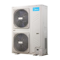
4.5 Centralized Chassis Drainage
While installing the outdoor unit, pay attention to the installation
place and the drainage pattern;
if it’s installed at the alpine zone, the frozen condensed water will
block up the water outlet, please pull out the rubber stopper of the
reserve water outlet. If that still fails to satisfy for the water draining,
please knock open the other two water outlets, and keep the water
can drain in time.
Pay attention to the knock the reserve water outlet from outside to
inside, and it will be beyond repair after knocking open, please pay
attention to the installation place, lest cause the inconvenience.
Please do the moth proofing for the knocked out hole, to avoid the
pest processing into and destroy the components.
CAUTION
When the outdoor unit requires centralized drainage, install the
chassis and two waterproof covers for the chassis, as shown in
Figure 4-7. Install the water outlet union pipe and sealing ring on
the chassis, and then connect the drainage pipe to complete
centralized drainage installation.
Sealing ring for the
water outlet union pipe
Waterproof chassis cover
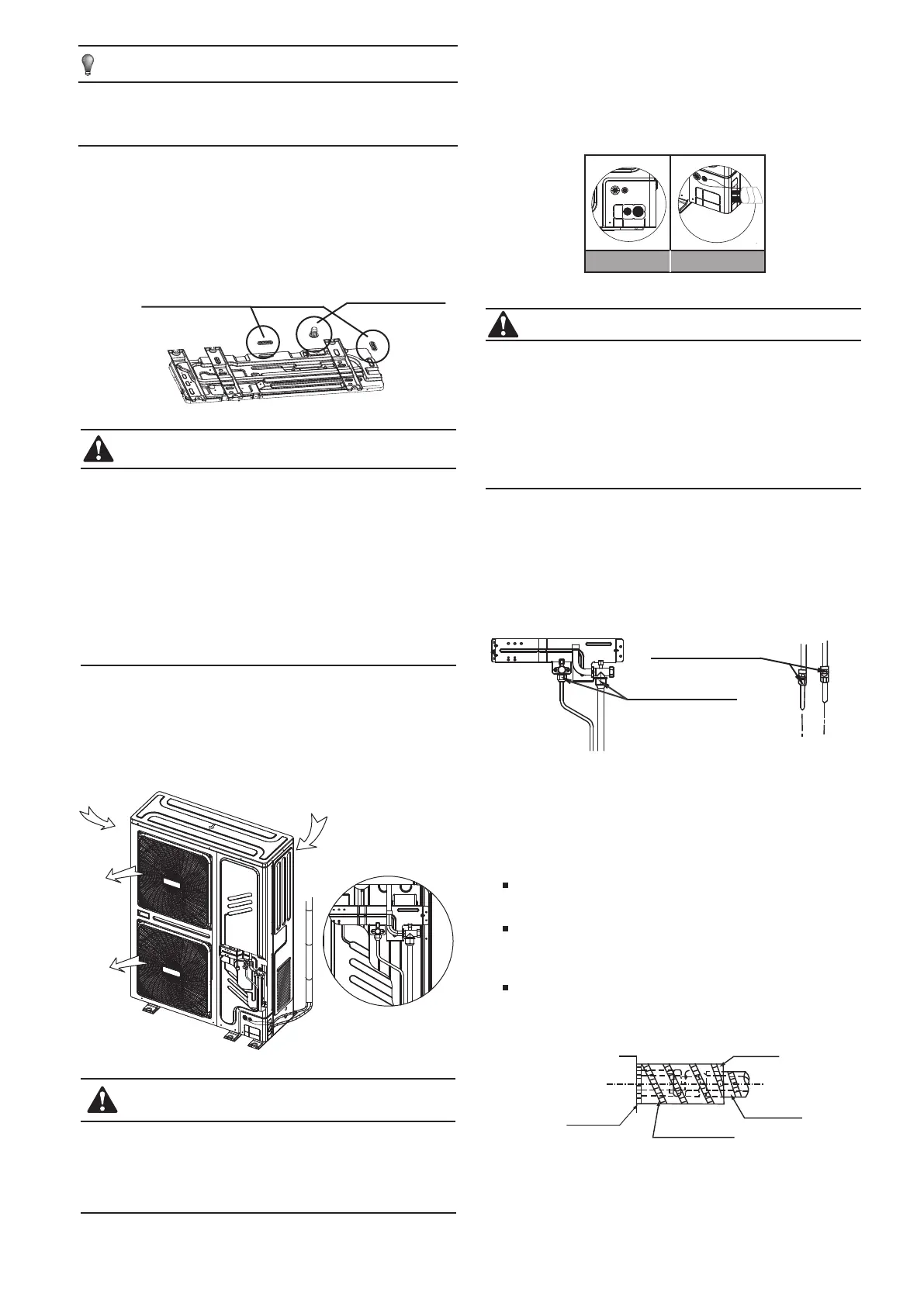
The indoor and outdoor connecting pipe interface and power
line outlet
Vavious piping and viring patterns can be selected,such as out from
the front ,the back the side ,and undersurface, etc.(The follow display
the locations of several piping and wiring knock-off interfaces)
Check whether the height drop between the indoor unit and
outdoor unit, the length of refrigerant pipe, and the number of
the bends meet the following requirements:
4.6 Install The Connecting Pipe Of Outdoor
Unit
Fig.4-8
Fig.4-11
The unit body
Affiliated heat pump belt
Site pipe side
Cut from upward
4.8 Heat Insulation
Do the heat insulation to the pipes of air side and liquid side
separately. The temperature of the pipes of air side and liquid side
when cooling, for avoiding condensation please do the heat
insulation fully.
The air side pipe should use closed cell foamed insulation
material, which the fire-retardant is B1 grade and the heat
resistance over 120°C.
When the external diameter of copper pipe≤Φ12.7mm, the
thickness of the insulating layer at least more than 15mm;
When the external diameter of copper pipe≥Φ15.9mm, the
thickness of the insulating layer at least more than 20mm.
Please use attached heat-insulating materials do the heat
insulation without clearance for the connecting parts of the indoor
unit pipes.
1. Side out pipe: cut the side hole of the pipe-outlet plate selectively.
It is suggested to cut a piece of metal plate below to avoid the mouse
come and destroy the machine wiring body.
2.Front out pipe: cut the frontal hole of the pipe-outlet plate selectively.
It is suggested to cut a piece of metal plate right side to avoid the
mouse come and destroy the machine wiring body.
3. Wiring of power cord: the strong and weak electrical wire should be
out through the two plastic holes of the pipe-outlet plate, and binded
with gas and liquid pipe together.
CAUTION
Use soap water or leak detector to check every joint whether leak or
not (Refer to Fig.4-10).Note:
A is low pressure side stop valve
B is high pressure side stop valve
C and D is connecting pipes interface of indoor and outdoor units
4.7 Leak Detection
Fig.4-10
Check point of outdoor unit
Check point of indoor unit
Front out pipe Side out pipe
D
C
A
B
6
To prevent the refrigerant piping from oxidizing inside when
welding, it is necessary to charge nitrogen, or oxide will chock
the circulation system.
CAUTION
Please pay attention to avoid the components while connect to
the connecting pipes.
Fig.4-9

 Loading...