M thermal Mono
40 202005
Midea M thermal Mono Engineering Data Book
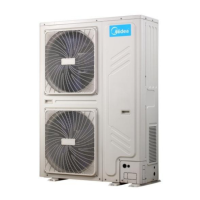
Figure 3-2.5: Outdoor unit typical concrete base structure design (unit: mm)
2.8 Drainage
Drainage ditch should be provided to allow drainage of condensate that may form on the air side heat exchanger when
the unit is running in heating mode or domestic hot water mode. The drainage should ensure that condensate is directed
away from roadways and footpaths, especially in locations where the climate is such that condensate may freeze.
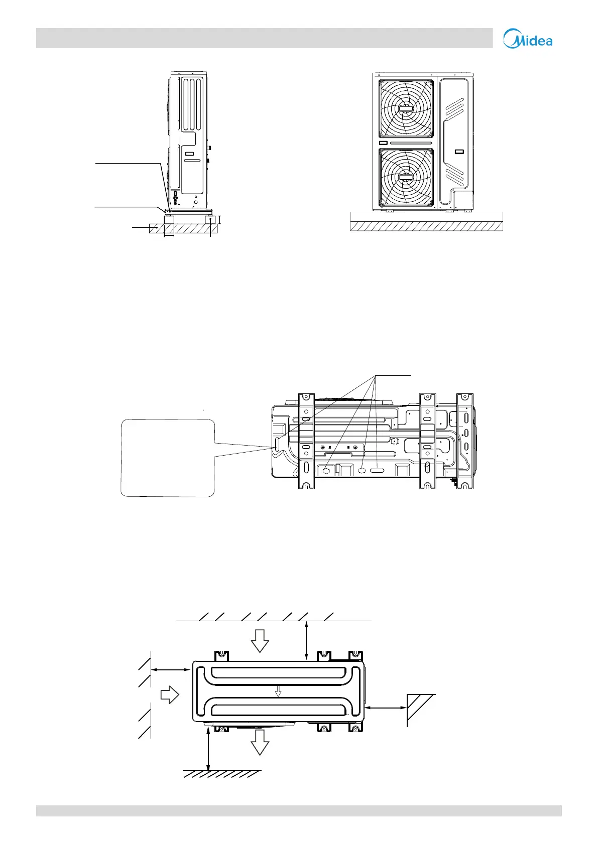
Figure 3-2.6: Drainage hole
2.9 Spacing
Outdoor units must be spaced such that sufficient air may flow through each unit. Sufficient airflow across heat
exchangers is essential for outdoor units to function properly. For more details please refer to the figures below.
Figure 3-2.7: Single unit installation
(unit: mm)
Concrete basement
h≥100mm
Rubber
shocking
proof mat
≥100
≥80
Φ 10 Expansion
bolt
Solid
ground
or roofing
This drain hole is
covered by rubber plug.
If the small drain hole
can not meet the
drainage requirements,
the big drain hole can be
used at the same time.
Drain hole
>300
>600
>
300
>
0
0
0
3
(Wall or obstacle)
Maintain the electric
wire and pipeline
Air outlet
Air inlet
Air inlet
 Loading...