Maintenance and
Disassembly
Page 31
Procedure Illustration
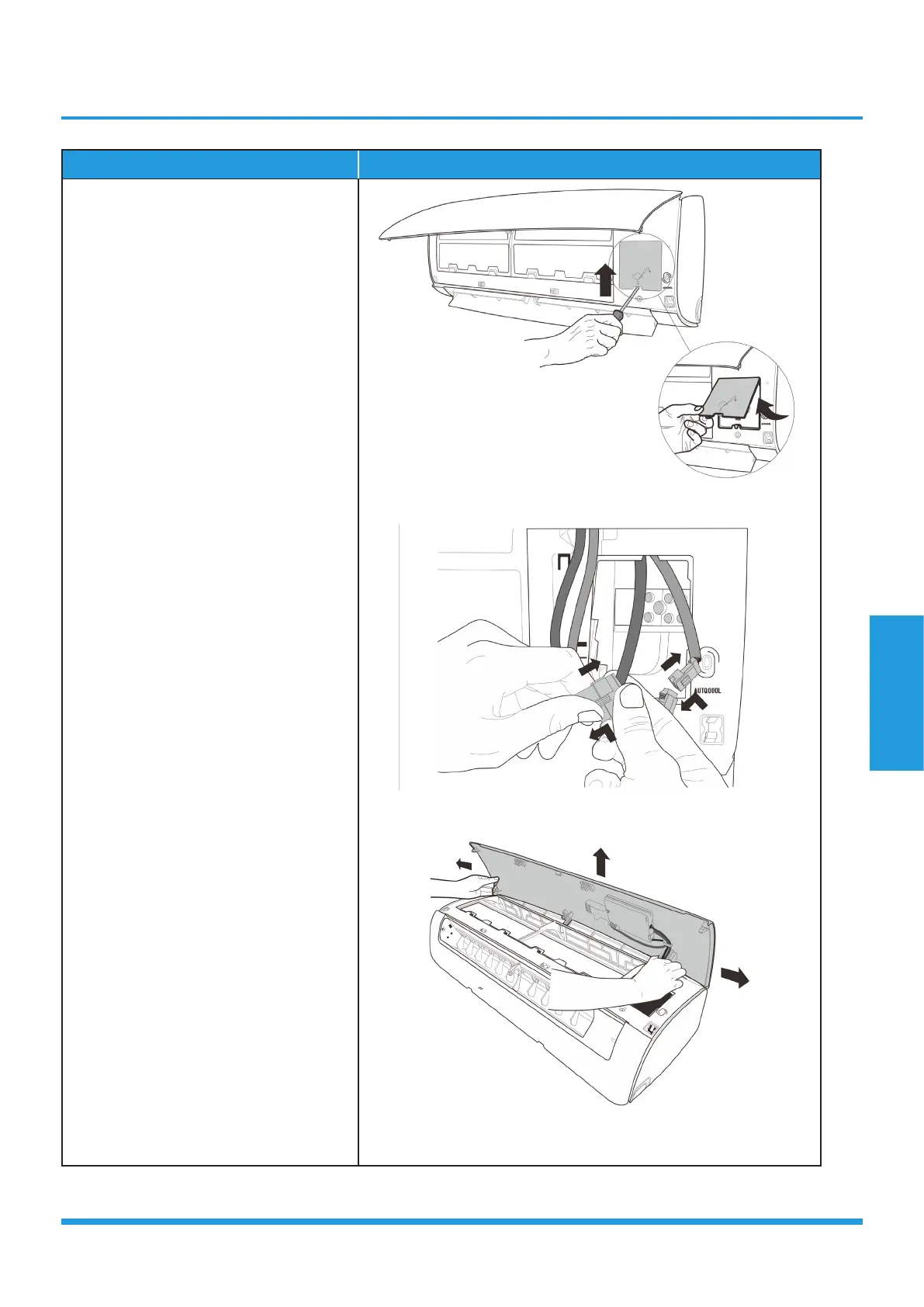
7) Remove 1 screw and then remove the
electrical cover(see CJ_MB1_INV_005).
8) Disconnect the two connectors for
display board and wifi model. (see
CJ_MB1_INV_006) .
9) Slid the front panel side to side to
release each axis (see CJ_MB1_
INV_007)
CJ_MB1_INV_005
CJ_MB1_INV_006
CJ_MB1_INV_007
Note: This section is for reference only. Actual unit appearance may vary.
 Loading...