24
Dryer
Safety
Operation
Requirements
Parts and
Features
Installation
Instructions
Dryer Use
Appendix
Dryer Care
Troubleshooting
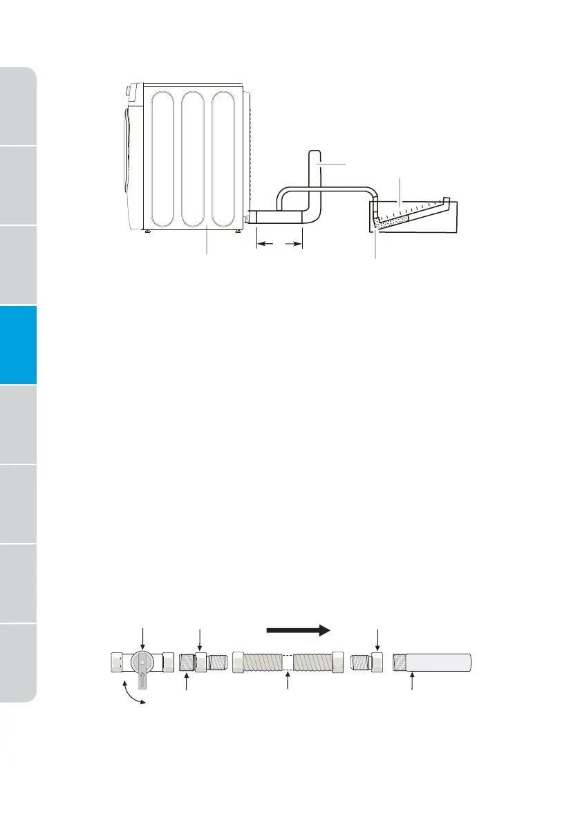
MEASURING AND VERIFYING ACTUAL SYSTEM BACK PRESSURE
a
b
c
d
a Dryer - empty and running on Air
Fluff cycle
b 10" (254 mm) min. of straight
pipe - measure back pressure
from the center
c To vent system
d Location on back
pressure measurement
e Inclined manometer
CONNECT THE GAS LINE (FOR GAS MODELS)
Review the “Gas Requirements” section on page 15. Remove the pipe
thread protective cap.
Apply a pipe joint compound or about 1 " wraps of teflon tape over all
threaded connections.
•
The pipe joint compound must be resistant to the actions of any
liquefied petroleum gas.
Connect the gas supply to your dryer. An additional fitting is required
to connect the " (1.9 cm) female thread end of a flexible connector to
the " (1 cm) male threaded end on the dryer. Use only new AGA or CSA
certified gas supply line with SS flexible connectors. within 6 ft (1.8 m) of
the dryer
Securely tighten the gas line fitting over the threads.
Turn on the gas supply.
S h u t o f f
V a l v e
Fl a r e
U n i o n
Fl a r e
U n i o n
O p e n
N i p p l e Fl e x i b l e
Co n n e c t o r
I n l e t P i p e o n
Ba c k o f Dr y e r
GAS FLOW
Al l c o n n e c t i o n s m u s t b e w r e n c h - t i g h t e n e d
 Loading...