MCAC-VTSM-2016-04 R410A DC Inverter VRF V4 Plus W Series 50Hz
Specification & Performance 23
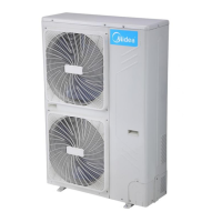
5.3 Signal wire of indoor/main units
Signal wire of indoor/main unit adopts 3-core shielded wire (≥0.75mm2) which has polarity, please connect it
correctly.
5.4 Electric wiring of water pipelines
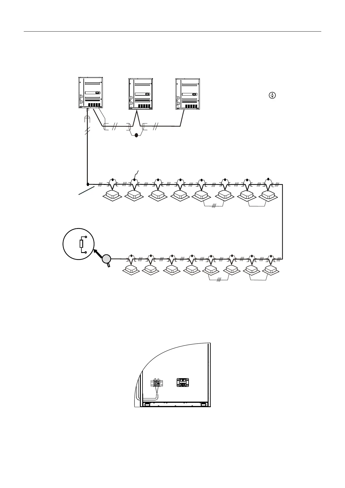
5.4.1 Water flow ON/OFF signal wiring
1) Water flow switch should be wired during the installation. Each unit must be configured a water flow switch,
and it cannot operate without a water flow switch.
2) The signal wire should apply 0.75mm2 shielding wire, and connected to the XT2 terminal in the electric
control box
Water flow ON/OFF signal input
Main unit
(master unit)
Main unit
(slave unit)
Main unit
(slave unit)
Signal wire between main units
(All shield terminals of shield wires
connect to COMM terminal )
(P Q E)
To closed end of shield wire
Signal wire of
indoor/main units
(open)
group control
P
Q
matching
resisitor
(P Q E)
(H1 H2 E)
(H1 H2 E)
(H1 H2 E)