Technical Information
3
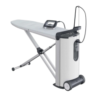
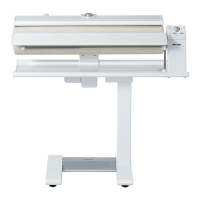
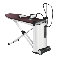
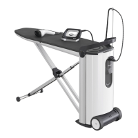
B 890/B 990
4.2 Heater Plate Motor (M18) Removal ............................................. 30
4.3 Hinge Pressure Spring Setting/Adjustment ................................. 30
035 Lifting Arm .............................................................................................. 32
3 Fault Repair ............................................................................................. 33
3.1 Emergency Release Does Not Allow Laundry to Be Removed ... 33
3.2 Heater Plate Cannot Be Lowered Completely ............................. 33
4 Service..................................................................................................... 33
4.1 Leaf Spring with Holder Replacement ......................................... 33
040 Roller ....................................................................................................... 35
3 Fault Repair ............................................................................................. 36
3.1 Laundry Not Taken In .................................................................. 36
3.2 Roller Does Not Turn or Only Turns with Difficulty ...................... 36
3.3 Roller Does Not Turn ................................................................... 36
3.4 Roller Stops or Heater Plate Does Not Start ............................... 36
4 Service..................................................................................................... 37
4.1 Roller Removal ............................................................................ 37
4.2 Ironing Cloth Replacement .......................................................... 38
050 Roller Motor ............................................................................................ 39
2 Function ................................................................................................... 40
2.1 Roller Drive/Motor ........................................................................ 40
2.2 Control Electronic ........................................................................ 40
3 Fault Repair ............................................................................................. 41
3.1 Noisy Operation in the Bearing Flange ........................................ 41
4 Service..................................................................................................... 41
4.1 Control Electronic (A1) Removal ................................................. 41
4.2 Drive Shaft Removal .................................................................... 42
4.3 Bearing Flange Removal ............................................................. 42
4.4 DC Motor Removal ...................................................................... 42
List of Figures
Figure D-1: Layout of Electrical Components ................................................................... 9
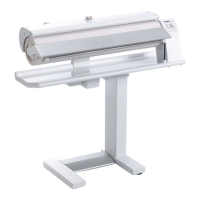
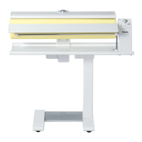
Figure D-2: Overview of Rotary Iron ............................................................................... 10
Figure D-3: Overview of (a) B 890 and (b) B 990 Controls ............................................. 10
Figure 010-1: Main Electronic N2, B 890 ........................................................................ 12
Figure 010-2: Main Electronic N2, B 990 ........................................................................ 13
Figure 010-3: Main Electronic Cover ............................................................................... 15
Figure 010-4: Main Electronic Screw .............................................................................. 15
Figure 010-5: Bowden Cable and Plastic Hinge ............................................................. 18
Figure 010-6: Bowden Cable Holder and Pulley ............................................................. 18
Figure 010-7: Bowden Cable Pin .................................................................................... 19
Figure 010-8: Handle Removal ....................................................................................... 20
Figure 020-1: Heater Electrical Circuit ............................................................................ 22
Figure 020-2: Heater Temperature Control ..................................................................... 22
Figure 020-3: Finger Guard ............................................................................................. 23
Figure 020-4: Handle (Locking Catch) ............................................................................ 24
 Loading...