Technical Information
9
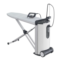
B 890/B 990
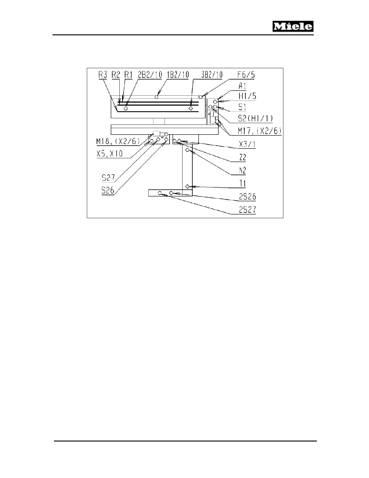
D Layout of Electrical Components
The layout for the B 890 and B 990 is also included in the wiring diagram.
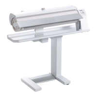
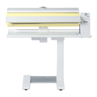
Figure D-1: Layout of Electrical Components
A1
Control panel/electronic
B2/10
Temperature control, heater plate
F6/5
Safety switch, finger guard
H1/1
On/Off LED
H1/5
Heating LED
M17
Roller motor
M18
Motor, heater plate drive
N2
Main electronic
R1-R3
Heater elements
S1
Selector switch
S2
On/Off switch
S26, 2S26
Switch, heater plate off roller
S27, 2S27
Switch, heater plate on roller
T1
Transformer
X2/6
Plug connector, motor
X3/1
Terminal block
X5, X10
Coupling
Z2
Interference suppression capacitor
 Loading...