7
WELDING TECHNIQUE
Setting of the machine
The setting of a MIG-MAG welding machine demands some practice from the welder, the machine having two
control points that have to conform. These two are the wire feed speed and the welding voltage. The welding
current is determined by the wire feed speed, and it should correspond to the workpiece. The current will
increase with increased wire speed, resulting in a shorter arc. Less wire speed will reduce the current and
lengthen the arc. Increasing the welding voltage hardly alters the current intensity, but lengthens the arc. By
decreasing the voltage a shorter arc is obtained with little change in current intensity.
When using CO
2
as shielding gas, increase the voltage by about 5 Volts per 100 Amp.
When changing the wire diameters, different control settings are required. A thinner wire needs more speed to
acquire the same current strength. A satisfactory weld cannot be obtained if extreme values are exceeded.
If the feed speed is too high for the welding voltage, blockage will occur in the torch as the wire dips into the
molten pool and does not melt. Welding in these conditions normally gives faults due to lack of fusion. If,
however, the welding voltage is too high, large drops will form on the end of the wire, causing spatter.
The correct setting of voltage and speed can be seen in an even and calm arc.
See tables.
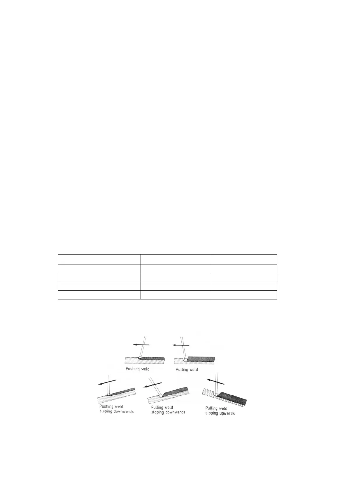
Influence of the welding position
The position of the torch and the work piece is important for the quality and appearance of the seam.
The diagrams on the next page show some of the many possibilities and indicate schematically the
importance of these positions. In practice one of course uses all combinations of welding positions, torch
directions and positions of the work piece.
Together with the figures, the diagram below may help when an estimation of the importance of separate
factors for welding quality is needed.
The terms drawing weld and thrusting weld mean:
Drawing weld: torch sloped in direction of weld
Thrusting weld: torch sloped away from direction of weld.
Drawing weld is sometimes designated "dragging welding" and thrusting weld "stabbing" welding
Thrusting weld Drawing weld
Width of seam wider narrower
Upper bead smaller larger
Penetration decrease increase
Tendency to lack of fusion greater lesser
 Loading...