13
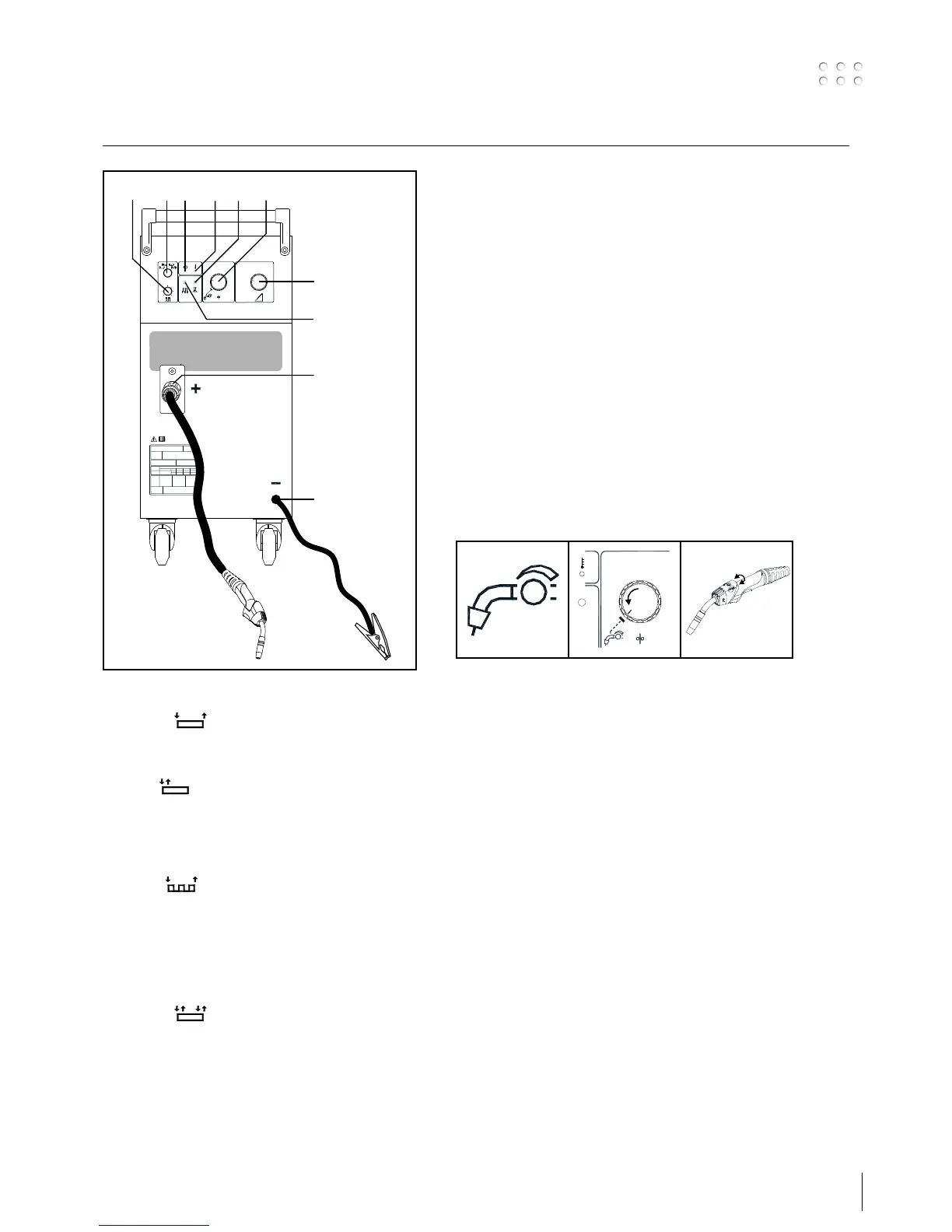
1. Switch:
2-times:
symbol
Start welding by pressing the trigger on the torch.
Welding continues until the trigger is released.
Spot:
symbol
The switch is set at Spot. When the trigger on the
torch is pressed, welding starts. Welding stops
automatically, depending on the time set on control
4 (0.15-2.5 secs.)
Stitch:
symbol
The switch is set at Stitch. When the trigger is
pressed, welding starts. The welding automatically
stops, depending on the time set on control 4. After
an interval fixed at control 5 the same cycle continues
automatically and only ceases when the trigger on
the torch is released.
4-times:
symbol
Welding starts the first time the trigger is pressed
(after which the trigger can be released) and
continues until the trigger is pressed again to stop
the welding process.
2. ON
Lights when the machine has been turned on.
3. Overheating
Lights if the welding process is automatically stopped due to
overheating of the transformer. The light extinguishes when
the transformer temperature has dropped to normal, and
welding can continue.
4. Welding time
With this control the welding time can be infinitely varied
between 0.15 and 2.5 secs when switch 1 is set to position
Spot or Stitch.
5. Pause time
With this control the pause time can be infinitely varied
when switch 1 is in position Stitch.
6. Burn back
Variable time delay for wire to stop feeding after voltage
is switched off. This function is used to prevent the wire
sticking to the workpiece or torch. Variable between 0.05
and 0.5 secs.
7. Wire feed speed control (internal/torch)
Selecting torch adjustment
 Loading...