5
Keypad Description
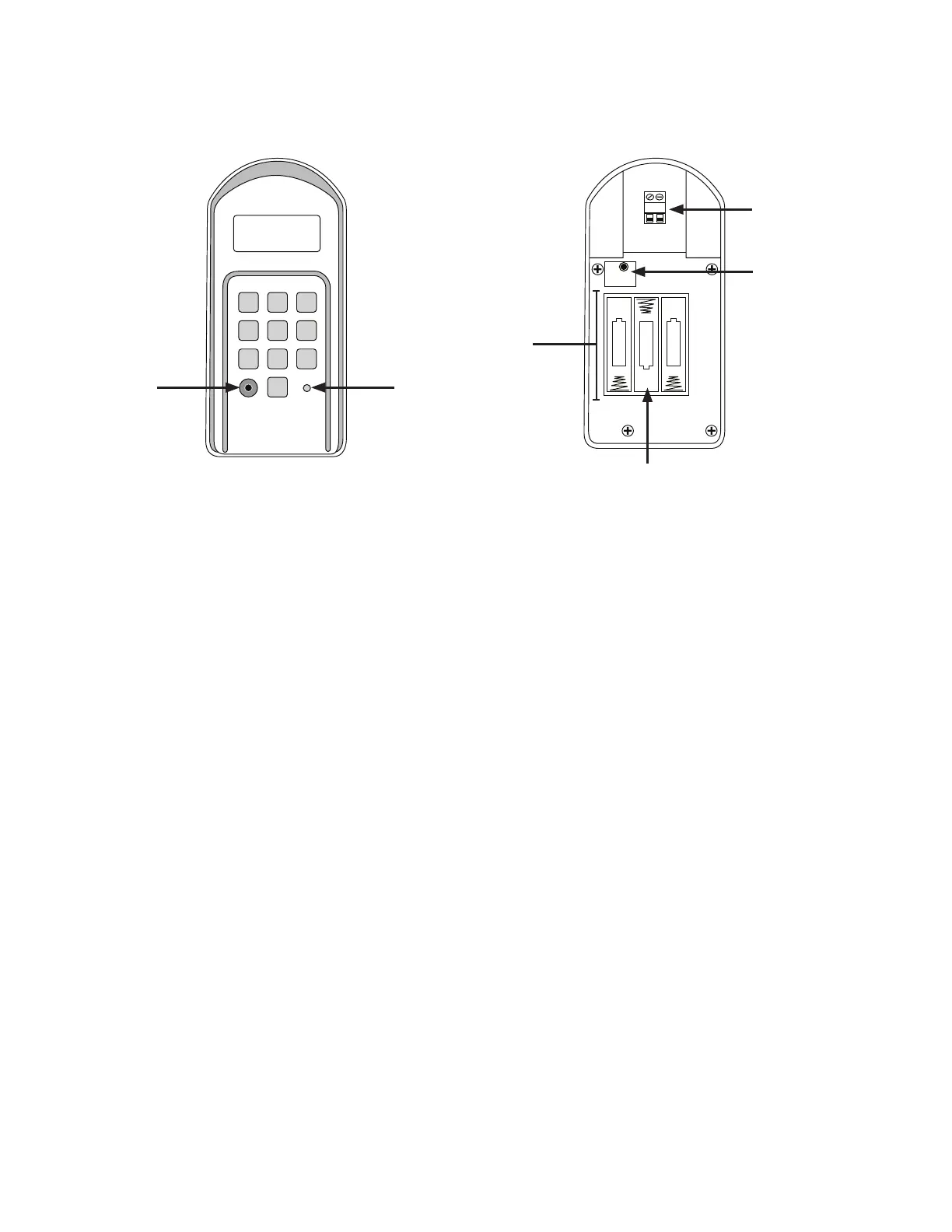
Front
1. Program button: Use for/during program process.
2. Status Light: The LED will blink once when any key is pressed and provides visual feedback during access code programming.
3. Open Collector Output: Used to connect Keypad to gate opener that accepts logic inputs (All NSC gate openers) in hard-wired
applications.
4. Reset button: To reprogram keypad to factory settings, press and hold the RESET button. When holding the RESET button down,
you will hear 1 initial beep, followed by a period of silence for ~5 seconds then 3 beeps in a row. Release the button after the 3
beeps at the end. All codes are deleted. Default master code is 1234.
5. Battery Holder: Use 4 AA batteries if hard-wired power supply is not used. If external power source is used the 4 AA batteries
will provide a back-up power source.
6. Installing Batteries
NOTE: 3 AA batteries are required to power the keypad.
Step 1: Remove the two screws from the bottom of the keypad (Figure 3) and separate the keypad from its housing.
Step 2: Install four (3) AA batteries (not included). (Figure 2)
NOTE: Choose wireless or wired installation (not both) and proceed to appropriate section.
1 2
ABC
3
DEF
4
GHI
5
JKL
6
MNO
7
PRS
8
TUV
9
WXY
0
OUT COM.
RESET
+
–
–
–
+
+
Inside
Figure 1 Figure 2