Do you have a question about the Miller Electric 280 NT and is the answer not in the manual?
Details potential hazards associated with arc welding processes, including electric shock and burns.
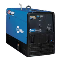
Covers safety warnings related to engine operation, including battery explosion, fuel hazards, moving parts, and hot parts.
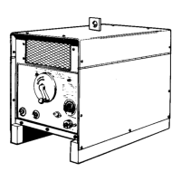
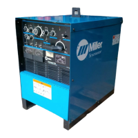
Details the welding output, generator power ratings, and engine specifications for the unit.
Instructions for safely mounting and securing the welding generator onto a vehicle or trailer.
Essential checks for engine fluids, fuel level, and battery condition before starting the unit.
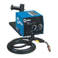
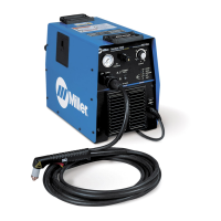
Guidance on correctly connecting weld cables to output terminals to prevent damage and ensure safety.
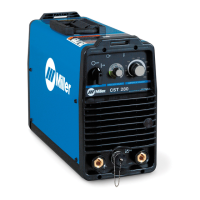
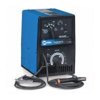
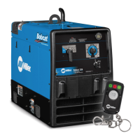
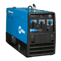
Overview and function of all controls and displays located on the front panel of the unit.
Guides for diagnosing and resolving common welding and generator operational issues.
| Input Voltage | 230/460 V |
|---|---|
| Input Frequency | 50 / 60 Hz |
| Duty Cycle | 60% |
| Rated Output | 280 A |
| Welding Processes | TIG, Stick |