
J
jose47Jul 29, 2025
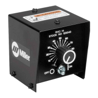
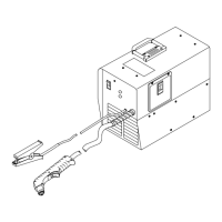
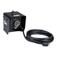
How to fix no amperage or voltage control on Miller Electric RHC-14 Welding System?
- DDawn AndersonJul 29, 2025
To resolve the issue of no amperage or voltage control in your Miller Electric Welding System, start by setting the switches and controls on the welding power source or generator. Then, check the weld output on the welding power source or generator. Finally, ensure that all cord connections are secure, replacing cords if needed.