Do you have a question about the Miller Electric Welder and is the answer not in the manual?
Explains the meaning of safety symbols used throughout the manual.
Details potential dangers associated with arc welding processes.
Covers symbols related to equipment installation, operation, and maintenance.
Lists key safety standards relevant to welding equipment.
Provides information on electromagnetic fields and potential health effects.
Explains the warnings found on the equipment's labels.
Defines common symbols used in the manual and on the equipment.
Details the information provided on the equipment's rating label.
Presents harmonic data according to IEC 61000-3-12 standards.
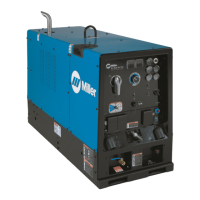
Lists the technical specifications of the welding unit.
Provides physical dimensions and weight of the equipment.
Guides on choosing a suitable and safe location for the equipment.
Illustrates how to connect the welding system components.
Details weld output terminals and guidance on selecting appropriate cable sizes.
Explains the 115V AC receptacle and associated circuit breakers.
Provides essential information for electrical service requirements.
Instructions on how to connect the unit to the input power source.
Describes the various connectors and ports on the rear panel.
Details the functions of the peripheral receptacle ports.
Explains the functionality of the touch sensor feature.
Covers the switch settings on the Touch Sensor Board PC18.
Step-by-step guide for connecting the setup pendant.
Defines key terms used for operating the welding unit.
Describes the controls located on the lower front panel of the unit.
Explains the functionality and display of the unit's meters.
Details the controls and indicators on the upper front panel.
Explains duty cycle limitations and overheating protection.
Illustrates the unit's voltage and amperage output capabilities.
Describes the buttons and displays on the setup pendant.
Outlines regular maintenance tasks for the equipment.
Instructions for cleaning the internal components by blowing out dust.
Steps for safely accessing and checking capacitor voltage.
Explains the help displays shown on the voltmeter/ammeter.
Lists and explains error messages displayed on the front panel.
Identifies diagnostic LEDs on the Weld Interface Board PC12.
Details the status and diagnosis for LEDs on PC12.
Identifies diagnostic LEDs on the Customer Interface Board PC14.
Details the status and diagnosis for LEDs on PC14.
Identifies diagnostic LEDs on the Motor Board PC13.
Details the status and diagnosis for LEDs on PC13.
Provides solutions for common operational problems.
Shows the electrical schematic for the welding power source.
Part 1 of the electrical schematic for Control Board PC1.
Part 2 of the electrical schematic for Control Board PC1.
Part 3 of the electrical schematic for Control Board PC1.
Electrical schematic for the Function/Meter Board PC3.
Electrical schematic for the Interconnect Board PC2.
Electrical schematics for Gate Boards PC4 and PC5.
Electrical schematic for the Interface Module.
Electrical schematic for the Microprocessor Board PC11.
Electrical schematic for the Motor Board PC13.
Electrical schematic for the Switch Board PC15.
Electrical schematic for the Junction Board PC16.
Part 1 of the electrical schematic for Interface Board PC12.
Part 2 of the electrical schematic for Interface Board PC12.
Part 1 of the electrical schematic for Customer Interface Board PC14.
Part 2 of the electrical schematic for Customer Interface Board PC14.
Part 3 of the electrical schematic for Customer Interface Board PC14.
Electrical schematic for the Touch Sensor Board PC18.
Electrical schematic for the Setup Pendant.
Electrical schematic for Setup Pendant Centronix Junction Board PC3.
Electrical schematic for the Power Distribution Board PC20.
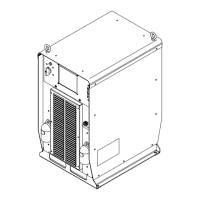
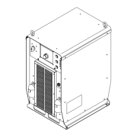
Exploded view diagram showing the complete assembly of the unit.
Continuation of the parts list with item numbers, descriptions, and quantities.
Lists parts specifically for the setup pendant accessory.
Details the factory-equipped programs for pulse MIG welding.
Lists standard pulse welding programs and their parameters.
Specific parameters for Program 1: 1.2mm steel with Argon-Oxy gas.
Specific parameters for Program 2: 1.0mm steel with Argon-CO2 gas.
Specific parameters for Program 3: 1.2mm steel with Argon-CO2 gas.
Specific parameters for Program 4: .8mm 316 with Argon-CO2 gas.
Specific parameters for Program 5: 1.0mm 316 with Argon-CO2 gas.
Specific parameters for Program 6: 1.2mm 316 with Argon-CO2 gas.
Specific parameters for Program 7: 1.0mm 308L with Argon-CO2 gas.
Specific parameters for Program 8: 1.2mm 308L with Argon-CO2 gas.
Specific parameters for Program 1: 1.2mm metal core with Argon-CO2 gas.
Specific parameters for Program 2: 1.4mm metal core with Argon-CO2 gas.
Specific parameters for Program 3: 1.2mm ER 4043 with Argon gas.
Specific parameters for Program 4: 1.0mm ER 4043 with Argon gas.
Specific parameters for Program 5: 1.0mm 5356 with Argon gas.
Specific parameters for Program 6: 1.2mm ER 5356 with Argon gas.
Specific parameters for Program 7: .8mm steel with Argon-Oxy gas.
Specific parameters for Program 8: 1.0mm steel with Argon-Oxy gas.
Explains how to use the Mode Select button on the setup pendant.
Guides on using the Parameter Select button on the setup pendant.
Describes how to adjust parameters using increase/decrease buttons.
Illustrates the sequence of events during a pulse welding cycle.
Instructions for setting the preflow time parameter.
Guidance on adjusting weld parameters like trim and wire feed speed.
Steps for configuring crater parameters like time, voltage, and wire feed speed.
Instructions for setting the postflow time parameter.
Explains the parameters that control the pulse waveform output.
Details the concept of teach points for creating custom pulse programs.
Guide on selecting wire feed speed for teach points.
Instructions for adjusting parameters at each teach point.
How to switch from standard pulse to adaptive pulse welding mode.
Illustrates the sequence of events during a MIG welding cycle.
Steps to switch the unit to MIG welding mode.
Instructions for setting the preflow time parameter for MIG welding.
Guides on configuring start parameters like voltage and wire feed speed.
Instructions for adjusting weld parameters like inductance and voltage.
Steps for configuring crater parameters like time and voltage.
Instructions for setting the wire retract parameters.
Guide on setting the postflow time parameter.
Instructions for enabling and setting run-in wire feed speed.
How to select and adjust the SharpArc setting for arc characteristics.
Instructions for physically installing the data card into the unit.
Overview of functions available when using the data card.
Steps for naming programs and saving them to the data card.
Instructions on how to transfer program data from the card to the unit.
Handling the scenario of reading from or deleting from an empty data card.
Steps for removing programs from the data card.
How to enable and use the security lock feature for programs.
A visual guide to navigating the setup menu options.
Explains how to interact with the setup displays and save changes.
Steps to set or modify the access code for setup displays.
How to configure voltage correction settings for arc stability.
Options for configuring the auxiliary output function.
Choosing between internal or external voltage sensing.
Options for Standard, Hot Start, or Soft Start methods.
How to reset the accumulated arc time or cycle count.
Setting wire feed speed units (IPM/MPM) and motor type.
Guides on selecting wire type (hardwire/softwire) and performing system reset.
Options for how measured values are displayed.
Procedures for resetting various memory settings, including system and program resets.
Configuring the unit's shutdown behavior based on arc start and voltage sensing.
Enabling the feature to name programs stored on the data card.
Configuring the unit for remote program selection.
Details the binary code for remote program selection.
Setting the wire feed speed for jog operations.
Enabling or disabling the flow switch input monitoring.
Configuring arc voltage error detection and acceptable deviation ranges.
Enabling or disabling the stick check routine performed after each weld.
Adjusting output power tapering for start and crater phases.
Displays the current software version of the unit.
Procedures for safely exiting the setup menu.
Describes how to navigate and use the control menu displays.
Adjusting the rise time to shape the pulse waveform.
Configuring adaptive parameters for arc length control.
Options for manual or automatic configuration via interface.
Enabling or disabling the wire retract feature.
Enabling or disabling the sharp start feature.
Procedure to exit the control menu.
Outlines the terms, conditions, and duration of the limited warranty.
Lists items and conditions not covered by the warranty.
Fields to record equipment details for personal records.
Provides contact details for service, parts, and training.
| Brand | Miller Electric |
|---|---|
| Model | Welder |
| Category | Welding System |
| Language | English |