B. SYSTEM COMPON
9081MRMB
ENT INSTALLATION (cont.)
9081MR
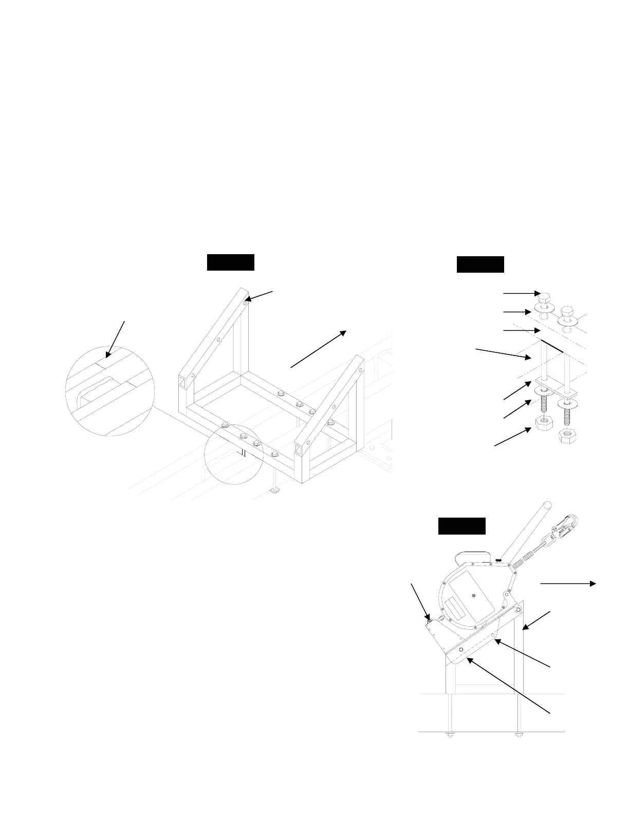
Locate the Installation marks stamped into the main frame rails located in the center of
Install a flat washer on the bolt, feed the bolt through both holes of the bracket along each
Install retaining strap, flat washer and hex nut. Tighten until snug then add 1/2 turn. Ref.
: All bolts must be installed to the above procedures prior to use. Failure to install all hardware
ote: Inspect for loose or damaged components prior to use. If any damage or loose hardware is
etected do not use system.
MB Installation:
Step 1.
the unit. Ref. fig. 4.
Step 2. Align and center the back of the bracket with the installation marks. Ref. figs. 4 & 5.
Step 3.
side of the frame rails. Ref. fig. 5
Step 4.
fig. 5. Caution: Over tightening will cause damage to retaining strap.
Warning
supplied could result in serious injury or death.
N
d
stalling the MightEvac Retrieval Units to the 9081MRMB:
he 9081MRMB at the
on shown and align the bottom holes. Ref. fig. 6
ompletely through both the bracket and
the tubin of the 9081MRMB.
passing under the 9081MRMB bracket ensuring the pin is completely through
both sides of the MightEvac bracket. Ref. fig. 6
of the sheave. Place the cable
e Edge unit and not
under, attach the carabiner to the pulley sheave and connect to the anchorage
point. (Eyebolts) Ref. fig. 1
Warning: Both pins must only be installed at location shown. Failure to install
sult in serious injury or death.
talled before using the system
In
Step 1. Place the MightEvac with attached bracket to t
locati
Step 2. Insert the bottom pin c
g
Step 3. Insert the second pin through the top installation hole of the bracket
Step 4. Open the pulley sheave by rotating half
on to the wheel of the pulley and close the pulley sheave.
5. Ensure that cable is over the steering handles of thStep
Disassembly: Reverse above procedures.
pins at these locations could re
Fig. 5
7/16” x 9” Bolt
7/16” Flat Washer
1MRMB Bracket
Fig. 4
Installation
Marks
Front of Unit
908
Frame Rail
Retaining Strap
7/
7/16” Hex Nut
16” Flat Washer
Fr ge
S
ont of Ed
stem
9081MRMB
Fig. 6
9081MRMB
Top
Ins on
Unit
Retaining Pin
tallati
Hole
Bottom
Installation
Hole
Note: Ensure the unit retaining pin is ins