Installing the ManHandler Hoist
hen standing behind Edge system the ManHandler can only
Bot
Installa
W
be installed on the left side of the 9081MRMB unit.
tep 1. Place the ManHandler to the 9081MRMB at the location
7
ce
close the pulley sheave.
carabiner to the pulley sheave and
sembly: Reverse above procedures.
re
ry or death.
the ManHandler follow instructions supplied with the unit at the
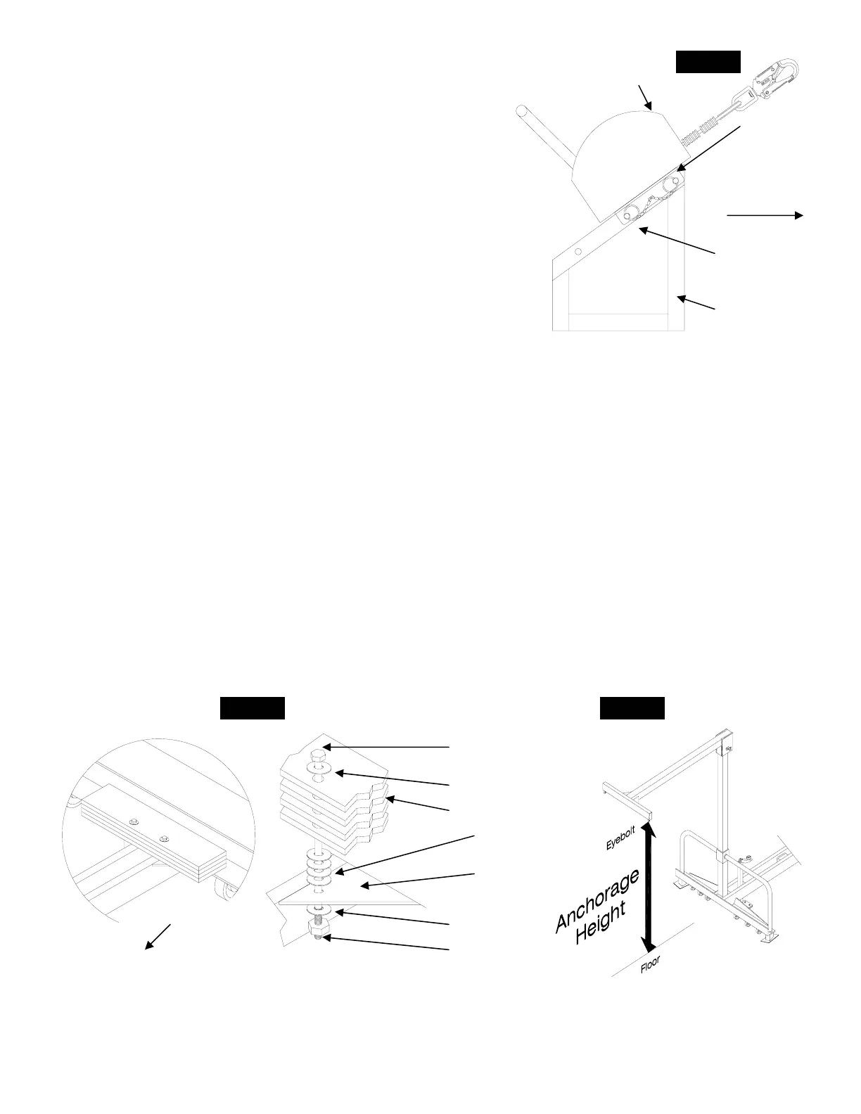
Step 2. Install the plates with (4) spacers on each side between the bottom plate and gusset. Ref.
and through
the gusset as shown in fig. 8
Warnin
serious
Warnin ermine
anchora
d do not use system.
7/16” x 6” Bolt
7/16” Flat Washer
nter Weights
Gusset
7/16” Flat Washer
7/1 ut
S
shown and align the top holes. Ref. fig.
Step 2. Insert the both pins completely through both the bracket and
the tubing of the 9081MRMB.
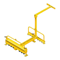
Step 3. Open the pulley sheave by rotating half of the sheave. Pla
e on to the wheel of the pulley andthe cabl
Step 4. Ensure that cable is over the steering handles of the Edge
unit and not under, attach the
connect to the anchorage
point. (Eyebolts) Ref. fig. 1
Disas
Warning: Both pins must only be installed at location shown. Failu
to install pins at these locations could result in serious inju
Note: For operation and maintenance to
time of shipment.
9081WT/300LB Counter Weight Installation:
Step 1. Locate the installation holes in the gussets in front of the I-beam. Ref. fig. 8
fig. 8
Step 3. Install a flat washer on the bolt, feed the bolt through the holes of each plate
flat washer and hex nut. Tighten until snug then add 1/2 turn. Ref. fig. 8 Step 4. Install
g: All (4) counter weights must be installed. Failure to install all counter weights may result in
injury or death.
g: Counter weights must be used for units with anchorage points higher than 8 ft.To det
e height reference fig. 9 g
Note: Inspect for loose or damaged components prior to use. If any damage or loose hardware is
detecte
Fig. 8
Cou
Spacers
6” Hex N
Front of Unit
Fig. 9
9081MRMB
ManHandler
Unit
Front o e f Edg
S
stem
tom
tion
Hole
Top
Installation
Hole
Fig. 7