EasyManuals Logo

Miller Multimatic 235 User Manual

Miller Multimatic 235
76 pages
To Next Page IconTo Next Page
To Previous Page IconTo Previous Page
Page #20 background imageLoading...
Page #20 background image
. A complete Parts List is available at www.MillerWelds.com
OM-283935 Page 16
SECTION 5 INSTALLATION
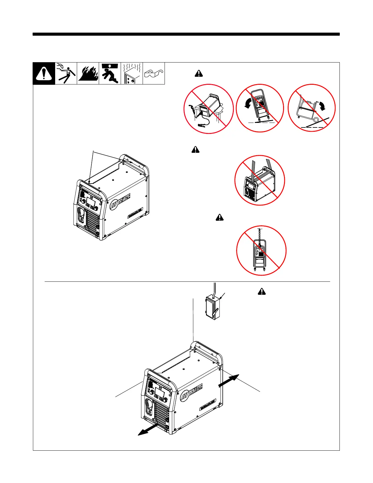
5-1. Selecting A Location
! Special installation may be
required where gasoline or
volatile liquids are present
see NEC Article 511 or CEC
Section 20.
1 Lifting Handles
Use handles to lift unit.
2 Line Disconnect Device
Locate unit near correct input
power supply.
18 in.
(460 mm)
18 in.
(460 mm)
2
! Do not move or operate unit where it could tip.
Movement
Location And Airflow
loc_smallmig2
2018-09 161-122
1
! Do not lift unit by strap threaded through both handles.
! Do not lift unit with cart attached.

Questions and Answers:

Question and Answer IconNeed help?

Do you have a question about the Miller Multimatic 235 and is the answer not in the manual?

Miller Multimatic 235 Specifications

General IconGeneral
Input Voltage120/240 V
Input Hz50 / 60 Hz
Max Output235 A
Welding ProcessesMIG, Stick, TIG, Flux-Cored
Wire Feed Speed Range50-700 IPM
Wire Size Range (Flux-Cored)0.030-0.045 in (0.8-1.2 mm)
Input PhaseSingle Phase
Wire Size Range (MIG)0.024 - 0.035 in

Related product manuals