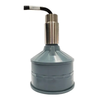
PL-551 XPS 10/15 F Series Transducer Page 15
Interconnection
Interconnection
Note:
Installation should only be performed by qualified personnel and in
accordance with local governing regulations.
Recommendations
• When using an XPS 15 F transducer, configure the electronic transceiver for
an XCT-12. These two transducers use the same settings.
• Do not route cable openly.
• For optimum isolation against electrical noise, run cable separately in a
grounded metal conduit.
• Seal all thread connections to prevent ingress of moisture.
• Do not run cable near high voltage or current runs, contactors and SCR
control drives.
Note:
In the interconnection examples that follow:
• an XPS 10 F Series transducer is shown. An XPS 15 F transducer can
also be used, but no hazardous seal is required.
• assume that the transducer is located in a Hazardous location (Class I,
Div. 1, Group A,B,C,D or Class II, Div. 1, Group E,F,G.) and the
transceiver in a Non-Hazardous (Safe) Location.
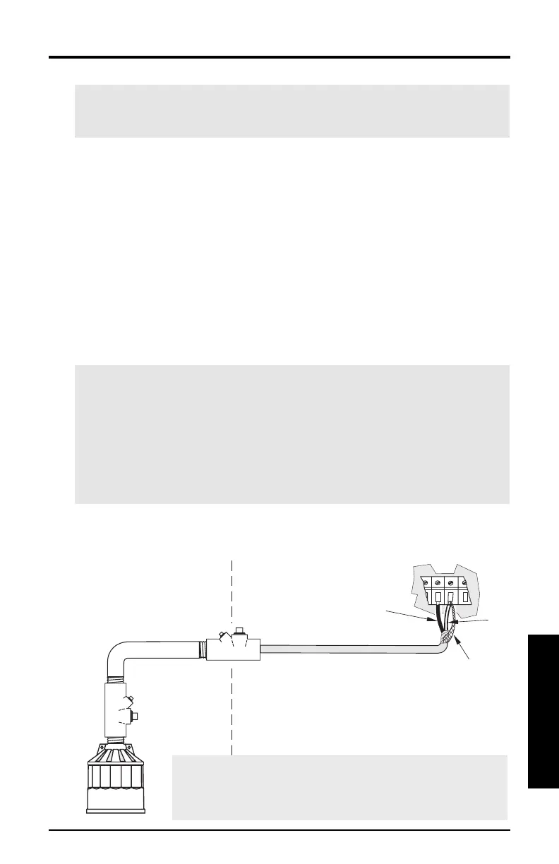
Direct Connection
(XPS 10 F shown)
metal conduit
bl
drain / shield
wht
Note:
When connecting to an EnviroRanger ERS 500, the
white, black, and shield wires are all connected
separately. Do not tie the white and shield wires together.
Hazardous Location
(Class I, Div. 1, Group
A,B,C,D or Class II, Div.
1, Group E,F,G)
Non-Hazardous Location
(Safe)