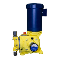
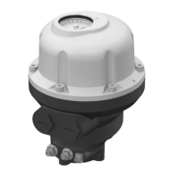
Do you have a question about the Milton Roy GM0025 and is the answer not in the manual?
Overview of the Series G Model M reciprocating chemical dosing pump's capabilities and design features.
Explanation of the drive assembly's variable eccentric mechanism and its conversion to linear motion.
Description of the diaphragm's mechanical linkage and its role in suction and discharge phases.
Details on flow rate, pressure, liquid end type, drive type, accuracy, lubrication, and temperature limits.
Guidelines for inspecting the pump upon receipt and procedures for both short-term and long-term storage.
Essential safety warnings and cautions for installation, operation, and maintenance of the pump.
Instructions for pump mounting and provisions for containing leaks in case of diaphragm or oil seal failure.
General guidance on installing the pump, including piping considerations and avoiding air traps.
Guidance on sizing suction piping to accommodate peak flow and general piping recommendations.
Best practices for suction line installation and guidelines for discharge piping to prevent pressure loss.
Details on back pressure, pulsation dampener, safety, and shut-off valves, plus electrical connection procedures.
Steps to verify pump mounting, oil level, valve positions, and capacity setting before start-up.
Procedure to check motor rotation direction against the housing flange marking.
Guidance on starting the pump and performing visual and audio checks for proper operation.
Methods for testing and calibrating pump capacity, including warnings for hazardous liquids.
Schedules for changing drive oil, and recommendations for replacing diaphragm, oil seal, and check valves.
Procedure for returning pumps for repair and guidance on routine checks for reliable operation.
Checking seal integrity, pump capacity, and diagnosing leaks from detection ports.
Diagnosing diaphragm or oil seal failure and information on stocking and ordering spare parts.
Lists of recommended spare parts for various liquid end models.
List of spare parts for GM0002-GM0050 liquid ends (PVC, PVDF, Stainless Steel).
List of spare parts for GM0090-GM0500 liquid ends (PVC, PVDF, Stainless Steel).
Procedures for addressing pump issues and performing repairs.
Methods for cleaning fouled check valves and general check valve replacement procedures.
Steps for replacing ball, seat, seal, and check valves in various liquid end configurations.
Instructions for replacing the diaphragm assembly and oil seal bellows.
Steps to follow after maintenance for safely reconnecting and restarting the pump.
Diagram and parts list for the GM drive side view, detailing components.
Diagram and parts list for the GM drive end view, detailing components.
Diagram and parts list for GM0002-GM0010 liquid ends with tubing connections for various fluids.
Diagram and parts list for GM0002-GM0010 liquid ends with LMI (PE) tubing connections.
Diagram and parts list for GM0002-GM0010 PVC liquid ends with threaded connections.
Diagram and parts list for GM0002-GM0010 stainless steel liquid ends with threaded connections.
Diagram and parts list for GM0002-GM0010 high viscosity liquid ends with tubing connections.
Diagram and parts list for GM0025-GM0050 liquid ends with tubing connections for various fluids.
Diagram and parts list for GM0025-GM0050 liquid ends with LMI (PE) tubing connections.
Diagram and parts list for GM0025-GM0050 PVC liquid ends with threaded connections.
Diagram and parts list for GM0025-GM0050 stainless steel and slurry liquid ends with threaded connections.
Diagram and parts list for GM0025-GM0050 high viscosity liquid ends with tubing connections.
Diagram showing the spacer for GM0090-GM0500 pumps.
Diagram and parts list for GM0090-GM0500 liquid ends for PVC, PVDF, and mixed fluids.
Diagram and parts list for GM0090-GM0500 stainless steel and slurry liquid ends.
Diagram and parts list for GM0090-GM0500 high viscosity liquid ends.
Sectional view diagram of double diaphragm leakage detection with a pressure gauge.
Sectional view diagram of double diaphragm leakage detection with pressure gauge and switch.
List of common parts for double diaphragm assemblies.
| Brand | Milton Roy |
|---|---|
| Model | GM0025 |
| Category | Water Pump |
| Language | English |
