Structure and Assembly/Disassembly of the Machine
1.4.6Disassembly of CRT, CRT adjustment board and the
connection board of the main unit
1. Disassemble the rear cover to take out the assemblies of the tail board and the
back board;
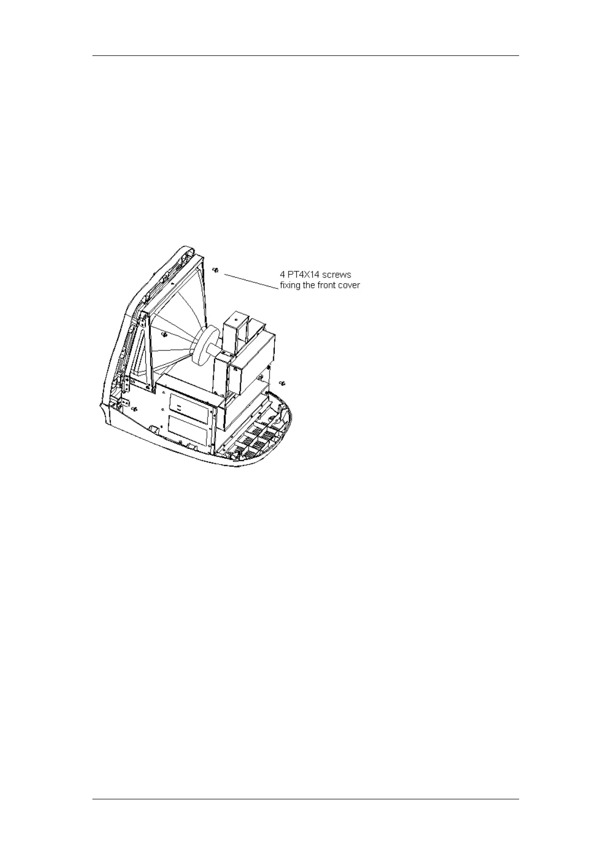
2. Remove 4 PT4X14 screws fixing the front cover;
Figure 2-23 Remove 4 PT4X14 screws fixing the front cover
3. Disconnect CRT signal cable, keyboard connection wire, CRT power wire and
CRT adjustment board connector;
DP-3300/DP-3200 Service Manual(V1.1) 2-17