Structure and Assembly/Disassembly of the Machine
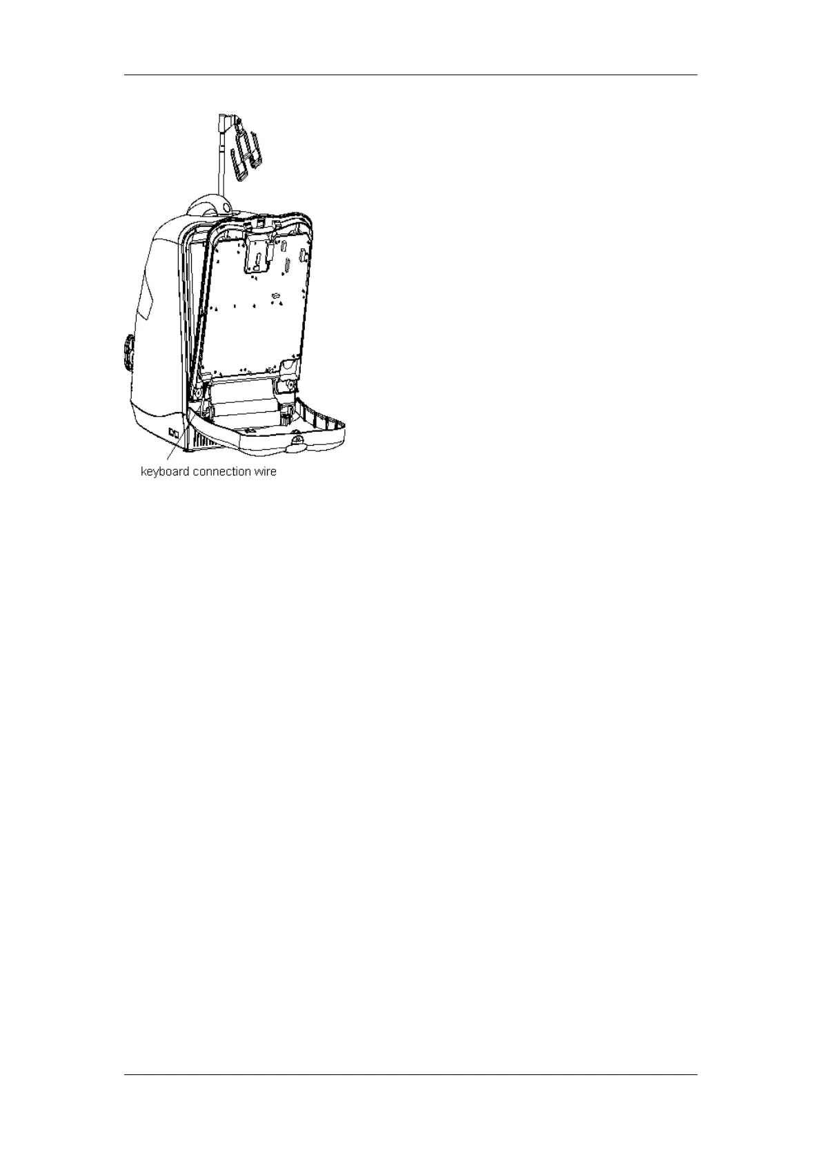
Figure 2-31 Disassembly of the keyboard upper cover
4. Disconnect the connection wire connector of the trackball, remove 4 ST3x14
self-threading screws fixing the trackball, and remove the trackball;
DP-3300/DP-3200 Service Manual(V1.1) 2-23