Part II General Information
Structure and Assembly/Disassembly 180
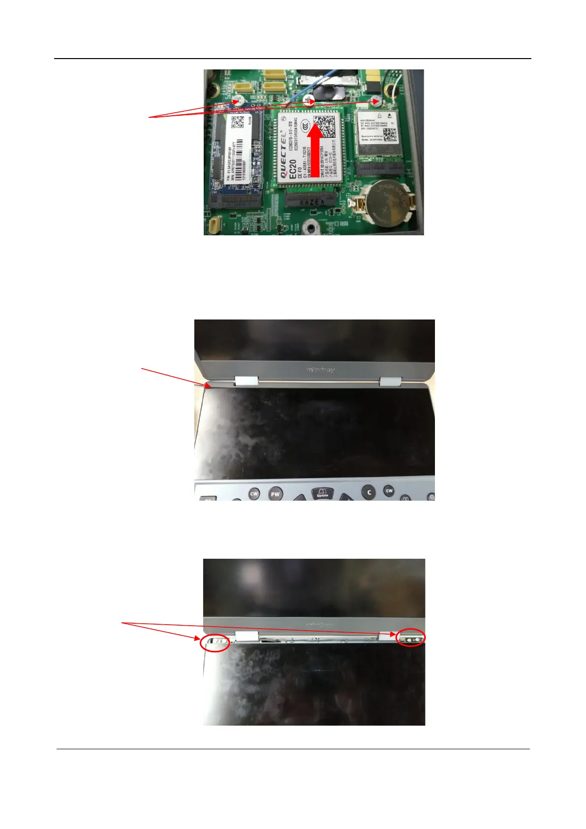
5.2.4 LCD and Keyboard Cover
1. Remove the spindle cover.
Insert a flathead screwdriver into the gap between the edge of the spindle cover and the keyboard
cover, and pull out the spindle cover.
2. Detach the LCD.
Use a crosshead screwdriver to remove the four M3X5 cross recessed flathead screws from the
damping axis, remove the signal cable softly, and then detach the LCD.
M3X5 cross recessed
flathead screw
Spindle cover
M3X5 cross recessed
flathead screw