Part II General Information
Function and Performance Check 232
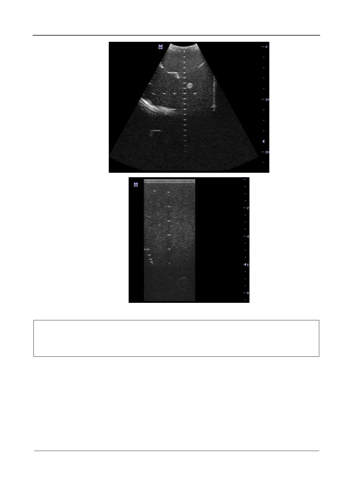
6.5.2.4 Axial Geometric Positioning Accuracy
Note:
Measuring cursor should be placed on the top edge of the target image, not in the middle
or bottom edge.
Scanning plane should be perpendicular to each target line, in other words, scanning
plane should be parallel to phantom section plane.
Test procedure:
1. Adjusting steps are the same with the Maximum Detection Depth.
2. Record the separation values with measuring caliper in step of 20 mm on the axial target group.
3. Select all measurement values deviating largely from 20 mm, and calculate the error by the
following formula.