Hardware Overview Theory of Operation
1 - 4 0070-10-0591-01 Trio™ Service Manual
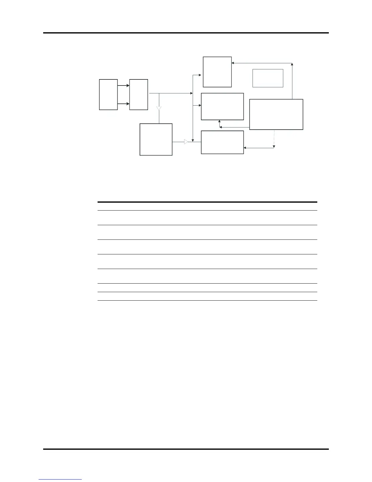
FIGURE 1-3 Block diagram of Trio power supply board
Key Test Points
NO. NAME LOCATION FUNCTION
1 Rectified voltage C12 Primary rectified voltage, range: 107~354 V
2 RTN1 C12 negative
electrode
Primary ground
3Driving
waveform
Q1.1 There is a driving waveform of about 100 KHZ
between Q1.1 and the negative electrode of C12
4 VIN C19 positive
electrode
17.5 V provide input voltage for DC-DC
5 GND C19 negative
electrode
Secondary ground
6 5B C47 positive
electrode
5 V spare output, provide power for on/off circuit
7 5 V ZD3 cathode 5 V output, voltage range is 4.75~5.25 V
8 12 V ZD3 cathode 12 V output, voltage range is 11.0~13.0 V
AC
input
AC/DC
12V output
REC POWER
SOURCE
Power on/off
test
Battery
and
Charging
Management
Circuit