Trio™ Service Manual 0070-10-0591-01 1 - 11
Theory of Operation Hardware Overview
1.2.6 Keypad Board
P/N 0671-00-0064
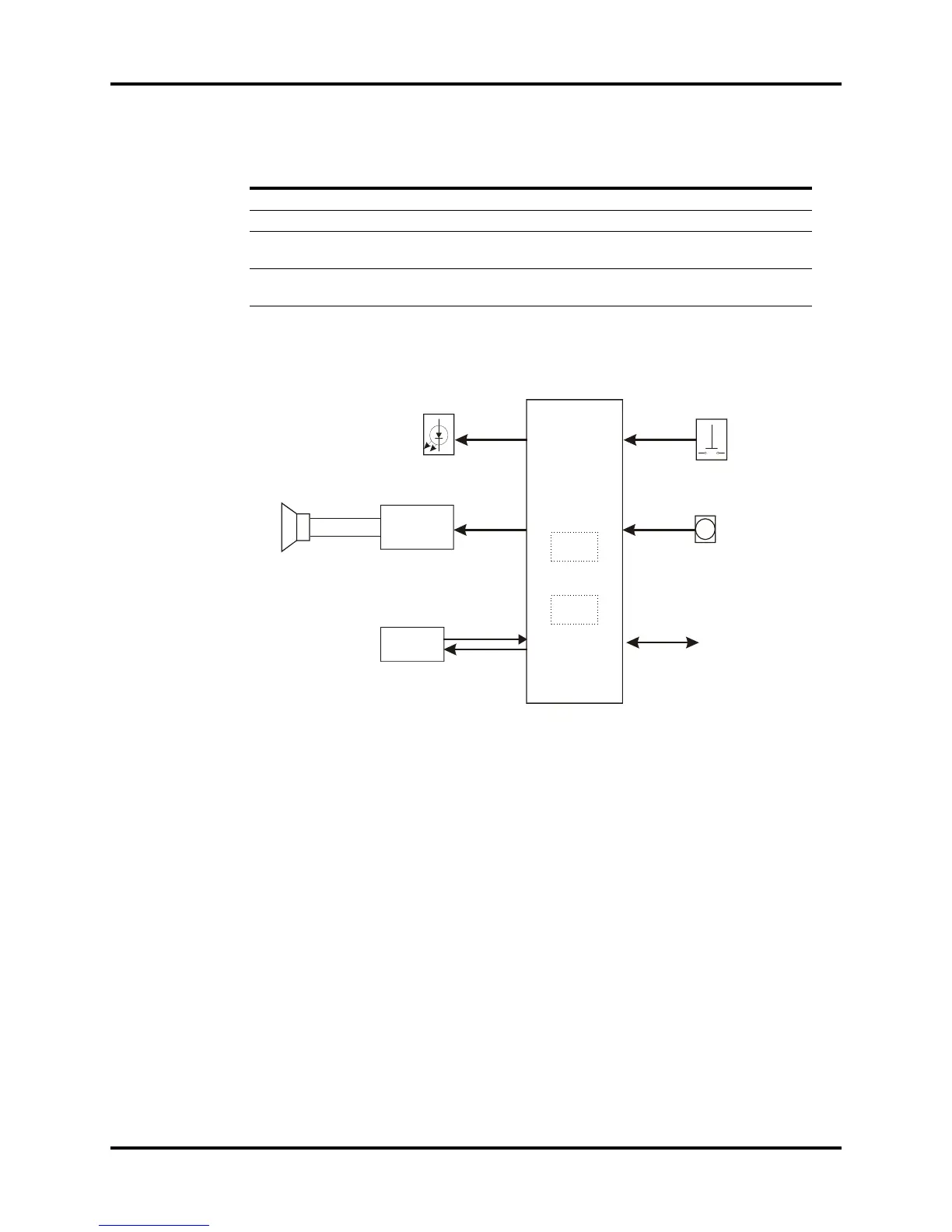
FIGURE 1-8 Keypad block diagram
1.2.6.1 Detailed Description
This module detects keypad and encoder input signals, converts them into code and transmits
the code to the Host CPU board. The Host CPU board sends commands to the keyboard
which in turn controls the indicator and audio process circuits, activating audio and visual
alarms accordingly.
CPU
The Keypad Board's CPU is responsible for the following functions:
• Detects keypad and encoder input signals
•Controls LED status
• Controls Audio Process Circuit
• Regularly zeroes Watchdog Timer
• Communicates with main board.
Key Test Points
NO. NAME LOCATION FUNCTION
1 VCC P4.4 Power input, range: 4.8~5.2V
2 GND P4.5 Power supply and signal ground
3 RST U1.10 CPU reset signal. At low level(<0.3V) when
operating normally
4 Crystal oscillator X1.1,X.2 CPU crystal oscillator. Sine wave signal
(1.5~3.5V) when operating normally
KEY
CPU
(PIC16F73)
RAM
192 X 8
FLASH
4K X 4
board (Host CPU Board)
Audio Process
Circuit
SPEAKER
LED