22 | minnkotamotors.com
©2023 Johnson Outdoors Marine Electronics, Inc.
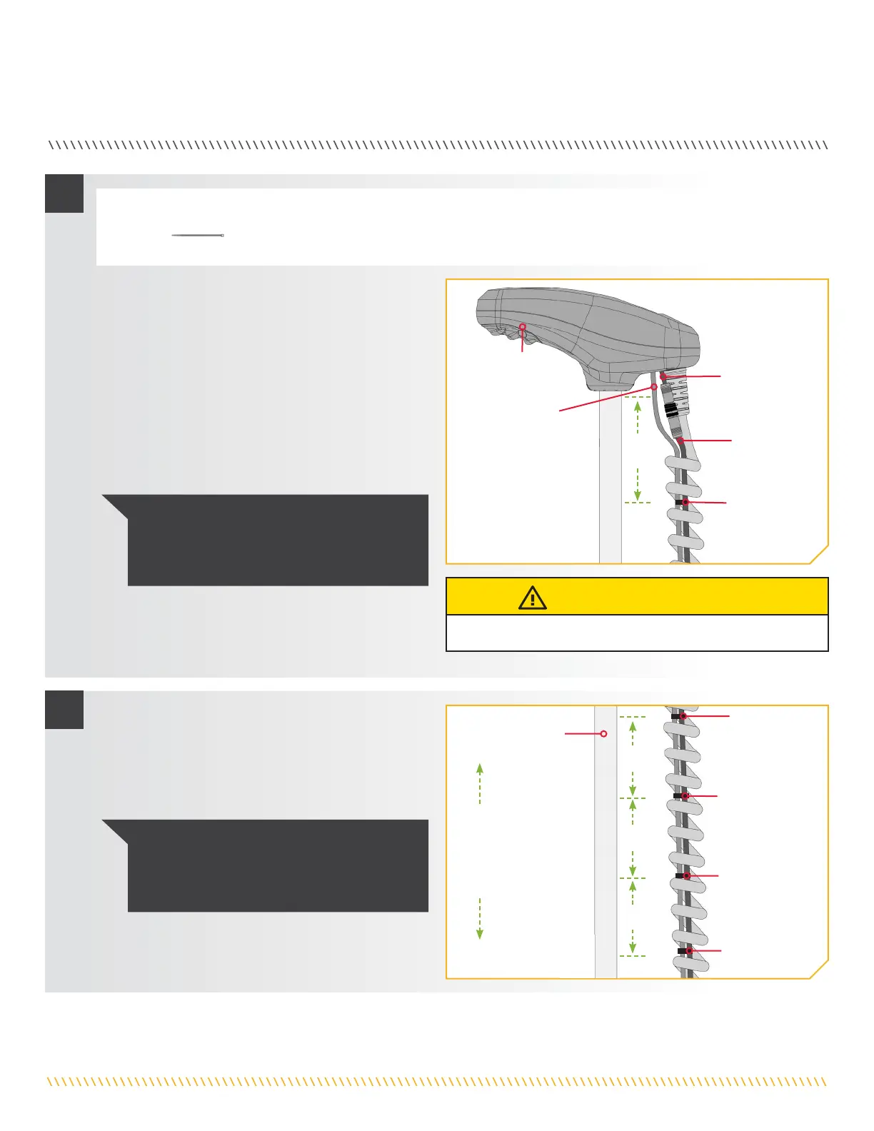
SECURING ACCESSORY CABLES
2
3
Control Control
HeadHead
Ethernet Ethernet
Cable or Cable or
Ethernet Extension Ethernet Extension
CableCable
Approximately Approximately
4 inches4 inches
Approximately Approximately
4 inches4 inches
Approximately Approximately
4 inches4 inches
c. Check the Accessory Cables and confirm that the
cables that are connected run parallel down the
center of the Coil Cord.
d. While the motor is in the stowed position,
straighten the Accessory Cables so they run
neatly from the Control Head to the Mount.
e. Starting approximately 4 inches below the
Control Head, take a Cable Tie (Item #16) and
place it around the Accessory Cables inside the
Coil Cord.
g. Follow the Accessory Cables from the Control
Head to the Mount and place additional Cable
Ties every 4 inches around the Accessory Cables
after the first Cable Tie. The number of Cable Ties
needed will vary depending on the length of your
trolling motor Shaft.
GPS Ethernet GPS Ethernet
ConnectionConnection
Cable TieCable Tie
ShaftShaft
First First
Cable TieCable Tie
Cable TieCable Tie
Cable TieCable Tie
Cable TieCable Tie
Advanced Advanced
GPS CableGPS Cable
NOTICE: Do NOT secure the Accessory Cables
to the Coil Cord. ONLY secure the Accessory
Cables with the Cable Ties to the other
Accessory Cables.
NOTICE: If additional Cable Ties are needed, a
Service Assembly (#2996300 TIE WRAP ASM,
60") is available from the Parts Ordering Portal
at
minnkotamotors.com.
f. Secure the Cable Tie around the Accessory
Cables until it is fingertip tight. Do not over-
tighten the Cable Tie as it will cause damage to
the Accessory Cables.
Control Control
HeadHead
MountMount
ITEM(S) NEEDED
#16 x 1
CAUTION
Do not over-tighten the Cable Ties as it may damage the wires.
Approximately Approximately
4 inches4 inches
 Loading...