Do you have a question about the MINN KOTA Riptide Ulterra and is the answer not in the manual?
Details on locating and using the motor's serial number for identification.
Crucial warnings for safe operation, propeller hazards, and user responsibility.
Explains limited warranties, exclusions, and limitations on coverage.
Information on how to obtain warranty service and authorized centers.
Comprehensive list of all parts required for motor installation.
Recommendations for optimal motor placement and clearance on the boat.
Essential tools and assistance needed for proper motor installation.
Steps for positioning and securing the motor to the boat deck.
Aligning the base extrusion with the gunwale and drilling mounting holes.
Using bolts and washers to attach the base extrusion to the boat.
Connecting the base extrusion to the boat deck using specified hardware.
Placing hardware on the damper side to secure the base extrusion.
Replacing the motor sideplates and securing them with screws.
Instructions for properly routing the i-Pilot Link cable to avoid damage and interference.
Steps for connecting the i-Pilot Link Ethernet cable to fish finder or switch.
Guidelines for rigging your boat and installing the trolling motor.
Table and guidance for selecting correct wire gauge and circuit breaker size.
Guidance on choosing the best batteries for optimal performance and longevity.
Notes on using DC/alternator chargers and accessories with trolling motor batteries.
Step-by-step instructions for wiring two 12V batteries in series for 24V operation.
Step-by-step instructions for wiring three 12V batteries in series for 36V operation.
Diagram illustrating the electrical connections for Riptide Ulterra models with i-Pilot or i-Pilot Link.
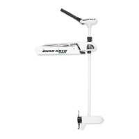
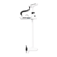
Familiarization with the motor's mounting components and their functions.
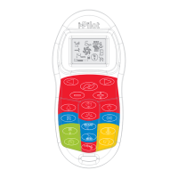
How to turn the motor on and off using the power button on the indicator panel.
Explanation of the LED indicators on the motor's indicator panel.
Functionality of the motor mount, mount ramp, and emergency strap.
Role of the belt collar in securing the lift belt for stowage and deployment.
Steps to deploy the motor using the i-Pilot system interface.
Steps to stow the motor using the i-Pilot system interface.
Procedures for deploying the motor via the i-Pilot Link remote.
Procedures for stowing the motor via the i-Pilot Link remote.
Using the Ulterra menu to initiate motor deployment and pausing.
Steps involved in the motor's automatic stow sequence and pausing.
Steps for stowing the motor using the i-Pilot Link system.
Steps for deploying the motor using the i-Pilot Link system.
Guidelines for routing the transducer cable, ensuring slack and avoiding damage.
Steps to prepare the motor for changing its propeller orientation.
Procedure for lifting and rotating the trim housing and shaft for orientation.
Reconnecting power and using stow/deploy to verify the new prop orientation.
How to adjust the lift belt tension using the socket head cap screw.
Recommended procedure for greasing critical motor components for optimal performance.
Steps to manually stow the motor and grease the latch pin.
Procedure to stow the motor using the base controls if the remote fails.
Steps to reset the motor's trim and stow functions if they malfunction.
Overview of alternative methods if remote/pedal stow fails.
Initial steps for manual stowage, involving removing the right sideplate.
Releasing the manual tilt knob and trim release handle for stowage.
Positioning the lower unit and securing it with the emergency strap.
Reinstalling the right sideplate after manually stowing the motor.
Step-by-step guide for removing and installing a new propeller.
Recommended practices for cleaning and lubricating the motor for longevity.
Guidance for diagnosing and resolving common motor operational problems.
Solutions for motor trim failures and issues with stowing or deploying.
Explanations for prop lockouts and audible error tones.
Diagnosing and fixing issues where the motor fails to power on.
Steps to ensure control panel switch/LED board is properly connected.
Verifying the power switch function and stow/deploy after repair.
Addressing cases where motor power cuts out due to low voltage or other issues.
Resolving issues where the motor does not respond to stow/deploy commands.
Identifying and correcting issues caused by damaged sensor wires.
Diagnosing and fixing problems related to binding or obstructions in motor movement.
Correcting motor issues related to the prop lockout region by trimming down.
Restoring the correct park position for the motor lower unit when stowing.
How to stop the stow sequence to manually adjust park position.
Manually rotating the motor lower unit to the correct park position.
Addressing errors where the motor fails to rotate correctly during stow/deploy due to lost position count.
Options for buying parts online, FAQs, calling service, and email support.
Information on locating and utilizing authorized Minn Kota service providers.
Statement on the company's commitment to environmental regulations and product disposal.
Information regarding i-Pilot and i-Pilot Link equipped motors' regulatory compliance.
Device compliance with FCC Part 15 rules for radio frequency interference.
Product adherence to Industry Canada technical specifications for radio interference.
Diagram and list for control head components.
Detailed list of parts for the control head assembly.
Exploded view diagram of the 24-volt, 4-inch motor components.
Detailed list of parts for the 24-volt, 4-inch motor assembly.
Exploded view diagram of the 36-volt, 4.5-inch motor components.
Detailed list of parts for the 36-volt, 4.5-inch motor assembly.
Exploded view diagram of the steering housing components.
Detailed list of parts for the steering housing assembly.
Exploded view diagram of the trim housing components.
Detailed list of parts for the trim housing assembly.
Exploded view diagram of the motor mount components.
Detailed list of parts for the motor mount assembly.
List of hardware, cables, and accessories for the motor mount.
List of various fasteners, clips, and standoffs for the motor mount.
Information on Minn Kota battery chargers designed to protect and extend battery life.
Introduction to the Talon shallow water anchor, its features, and control options.
Overview of various accessories available for Minn Kota trolling motors.
| Auto Stow/Deploy | Yes |
|---|---|
| Power Trim | Yes |
| Saltwater Use | Yes |
| Blade Material | Composite |
| Deploy/Stow | Automatic |
| Spot-Lock | Yes |
| Thrust | 80 lbs |
| Voltage | 24V |
| Shaft Length | 45" |
| i-Pilot Link | Yes |
| i-Pilot | Yes |
| Remote Control | Wireless |