minnkotamotors.com | 17
©2019 Johnson Outdoors Marine Electronics, Inc.
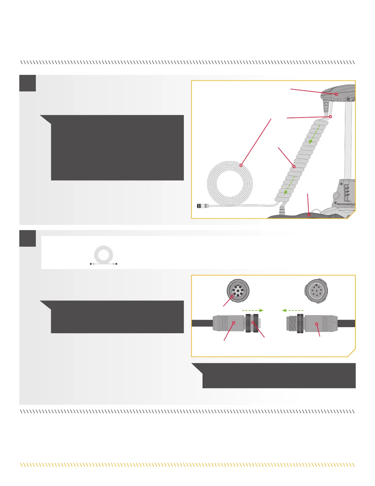
ROUTING AND CONNECTING I-PILOT LINK CABLESii
c. The i-Pilot Link cable should be fed all the way
through the Coil Cord. They should exit the Coil
Cord at the bottom of the Coil Cord, where it
connects to the Motor Mount.
Control Head
Coil Cord
Mount
i-Pilot
Link
2
NOTICE: After the i-Pilot Link Cable exits
the Coil Cord, it should be routed through an
established routing system on the boat, in an area
with minimal interference. Inspect the selected
route carefully to ensure that there are no sharp
edges, obstacles, or obstructions that may damage
the cables.
d. If necessary, to reach the installed fish finder, take the
i-Pilot Link Ethernet Cable (Item #14) and attach it to
the i-Pilot Link cable exiting the Control Head.
e. Install the i-Pilot Link Ethernet Cable directly into
the Humminbird fish finder, or refer to your fish
finder installation manual for complete installation
instructions. If an Adapter Cable is needed (Ethernet
Adapter Cable AS EC QDE for Helix fish finders),
install it on the end of the i-Pilot Link Ethernet
Cable and refer to your fish finder installation
manual for complete installation instructions.
3
i-Pilot Link Ethernet
Cable from Control Head
i-Pilot Link Ethernet
Extension Cable OR
Ethernet Adapter Cable
Locking
Collar
Eight Pin
Connector
#14 x 1
ITEM(S) NEEDED
NOTICE: If any cables need to be routed, please
follow the guidelines in the Routing Connection
Cables section of these installation instructions.
NOTICE: The connectors are keyed to prevent
reversed installation.
 Loading...