46 | minnkotamotors.com ©2023 Johnson Outdoors Marine Electronics, Inc.
CONNECTING THE BATTERIES IN SERIES
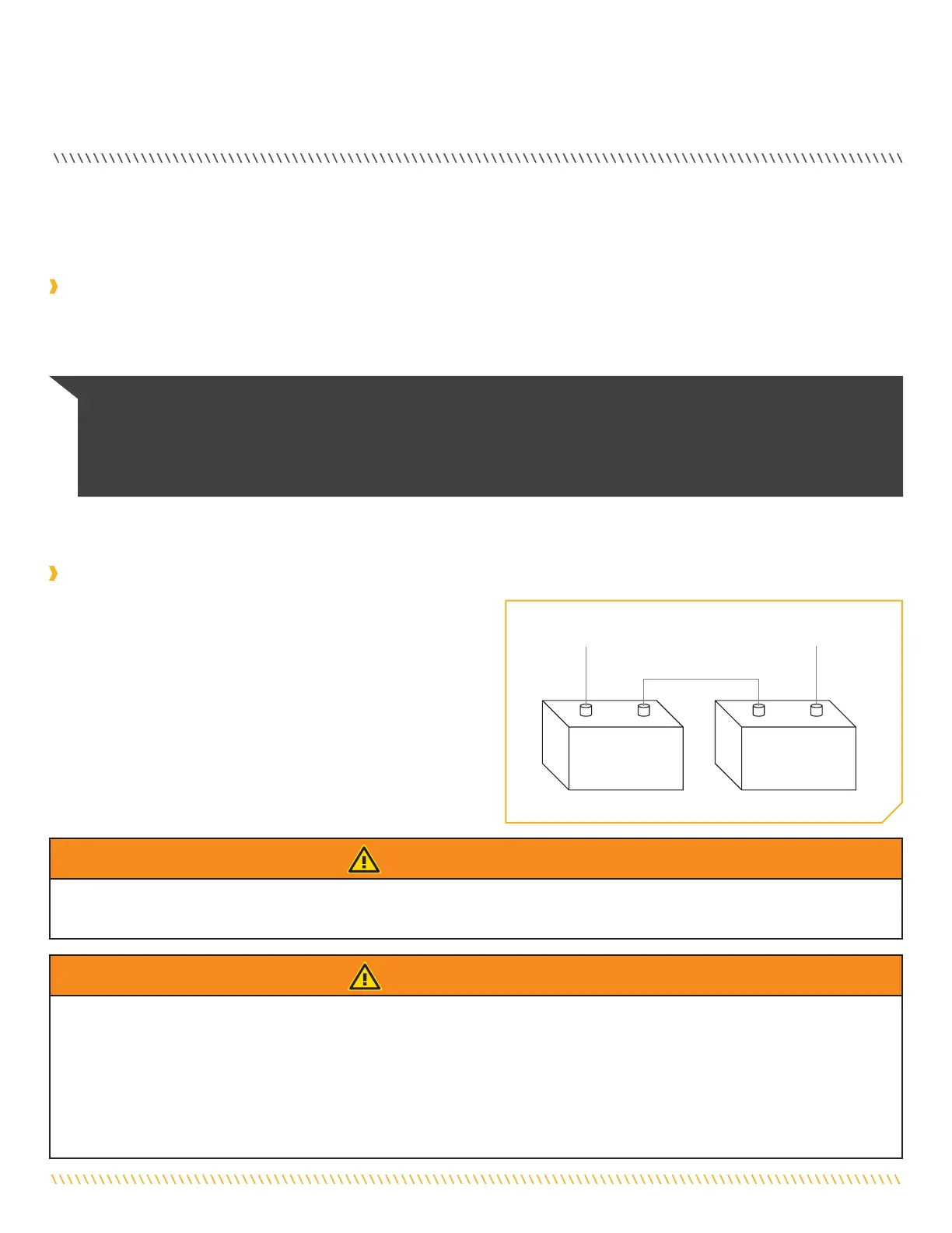
Automatic jump start systems and selector switches tie the negatives of the connected batteries together. Connecting these systems
to the “High Side” Battery or “Middle” Battery in the diagrams below and will cause significant damage to your trolling motor and
electronics. The only trolling motor battery that is safe to connect to one of these systems is the “Low Side” Battery.
Automatic Jump Start Systems and Selector Switches
NOTICE: The internal bonding wire is equipped with a 3-amp fuse. Improper connections described above carrying in excess of
3 amps will blow this fuse and no further damage will be exhibited. If this occurs, RF interference from the trolling motor aecting
sonar units and other electronics will be more significant. If the fuse is blown the wiring error should be found and addressed prior to
replacing the fuse. The replacement fuse should be 3 amps or less. An intact fuse does not imply correct rigging; significant damage
can be done by incorrect wiring without approaching 3 amps of current.
CONNECTING THE BATTERIES IN SERIES
(IF REQUIRED FOR YOUR MOTOR)
24-Volt Systems
Two 12-volt batteries are required. The batteries must be wired in
series, only as directed in the wiring diagram, to provide 24 volts.
1. Make sure that the motor is switched o (speed selector on “0”).
2. Connect a connector cable to the positive ( + ) terminal of
battery 1 and to the negative ( – ) terminal of battery 2.
3. Connect positive ( + ) red motor lead to positive ( + ) terminal
on battery 2.
4. Connect negative ( – ) black motor lead to negative ( – ) terminal
of battery 1.
To trolling motor negative
24 Volt Series Connection
Battery #1
(Low Side)
Neg - Neg -Pos + Pos +
Battery #2
(High Side)
+24 Volts to trolling motor
positive (or circuit breaker)
Two 12-volt batteries connected in series for 24 volts
WARNING
For safety reasons do not switch the motor on until the propeller is in the water. If installing a leadwire plug, observe proper polarity and
follow instructions in your boat owner’s manual.
WARNING
• For safety reasons, disconnect the motor from the battery or batteries when the motor is not in use or while the battery/batteries
are being charged.
• Improper wiring of 24/36 volt systems could cause battery explosion.
• Keep leadwire wing nut connections tight and solid to battery terminals.
• Locate battery in a ventilated compartment.
The negative (-) connection must be connected to the negative terminal of the same battery that the trolling motor negative lead connects
to. In the diagrams below this battery is labeled “Low Side” Battery. Connecting to any other trolling motor battery will input positive
voltage into the “ground” of that accessory, which can cause excess corrosion. Any damage caused by incorrect connections between
battery systems will not be covered under warranty.
 Loading...