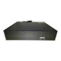
7
6
Output Power Receptacles
NEMA 5-15P W/6 ft cord
Model # Input Power Plug
EP500LCD
EP700LCD
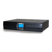
EP1000LCD
EP1500LCD
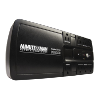
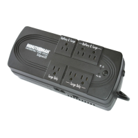
6-NEMA 5-15R Battery Backup & Surge
2-NEMA 5-15R Surge Only
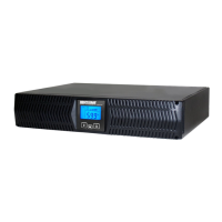
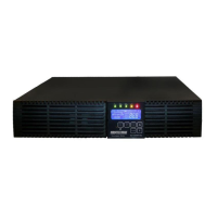
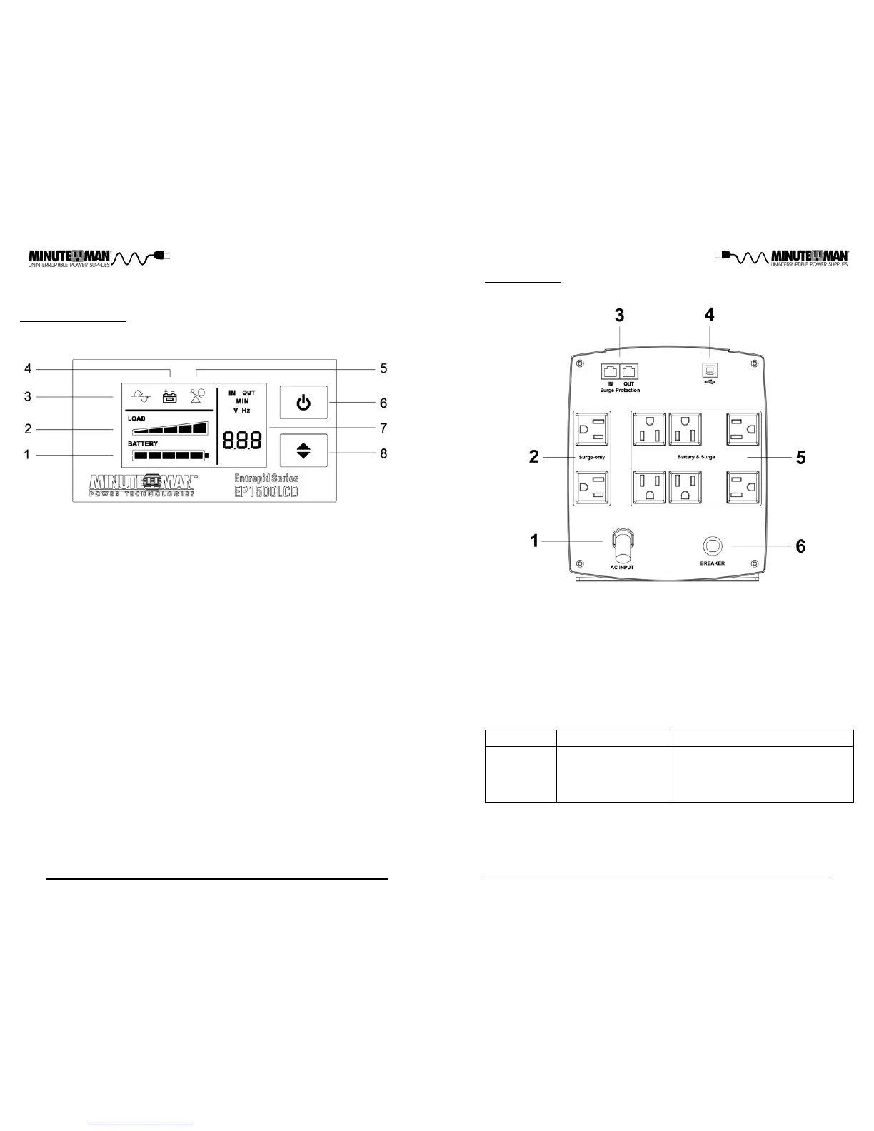
REAR PANEL
1. Input power cord: Connecting to the Utility Power.
2. Surge-only output receptacles: Noncritical equipment.
3. The RJ11/45: Phone/fax/network protection.
4. USB Communications Port: UPS monitoring and control.
5. Battery Backup & Surge output receptacles: Mission critical equipment.
6. Input circuit breaker: Protection against an excessive overload.
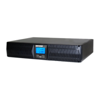
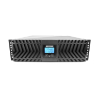
1. Battery Capacity Bar Graph: Displays the amount of Battery Capacity avail-
able in the AC and Battery mode.
2. Load Capacity Bar Graph: Displays the amount of load connected to the
UPS in the AC and Battery mode.
3. AC normal and Boost/Buck mode Icon: Illuminates when the UPS is in the
AC normal mode and flashs when the UPS is in the Boost or the Buck mo-
de.
4. On-Battery Icon: Illuminates when the UPS is operating in the Battery mode.
5. Overload Icon: Illuminates when the amount of load attached to the UPS ex-
ceeds its power rating,
6. On/Off/Test Button: To turn the UPS On/Off and to perform a ten-second b-
attery test.
7. UPS Parameters and Error codes:
Input - Voltage and Frequency.
Output - Voltage and Frequency.
Estimated Runtime (minutes) - AC normal and Battery mode.
S.L.F - A site wiring fault has been detected.
FAL - An internal fault has been detected.
8. Scroll Button: To scroll through the UPS parameters.
CONTROL PANEL
Chapter 2: Controls and Indicators
 Loading...