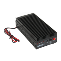
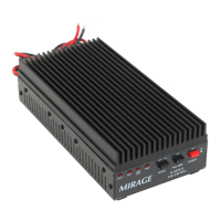
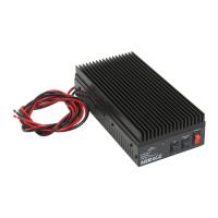
MIRAGE BD-35 Dual Band Amplifier
2
SPECIFICATIONS:
FREQUENCY: 144 TO 148MHz / 430 TO 450MHz
RF INPUT: 0.3 - 7 watts
RF OUTPUT: Up to 35 watts at 440MHz and up to
45 watts at 144MHz
DUTY CYCLE: INTERMITTENT (ICAS)
MODES: F3 (FM)
KEYING: AUTOMATIC SENSING
SUPPLY VOLTAGE: 12 -15 Vdc
RF CONNECTORS: TWO (2) SO-239 UHF
SUPPLY CURRENT; 7 AMPS TYPICAL
FUSE: 8 AMP, FAST BLOW
INPUT/OUTPUT IMPEDANCE: 50 OHMS
EXPLANATION OF FEATURES:
•
••
•
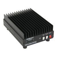
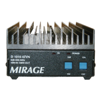
VHF ON AIR LAMP
This LED indicates that the power amplifier is transmitting in the VHF
(144 - 148MHz) band.
•
••
•
UHF ON AIR LAMP
This LED indicates that the power amplifier is transmitting in the UHF
(430 - 450MHz) band.
•
••
•
POWER ON LAMP
When the power switch is engaged the amplifier will illuminate the
POWER ON
lamp. This lets you know that the amplifier is ready to
amplify any signal of the proper frequency applied to its input.
•
••
•
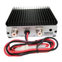
ANT (RF OUTPUT)
The coax from your antenna is connected to this port.
•
••
•
RADIO (RF INPUT)
The coax from your radio or exciter is connected to this port.
•
••
•
DC PWR (13.8V)
This port has two wires. The
Red
wire is for positive and incorporates a
FUSE holder. The
Black
wire is for negative. The Mirage BD-35
amplifier will accept from 12 to 15 Vdc.