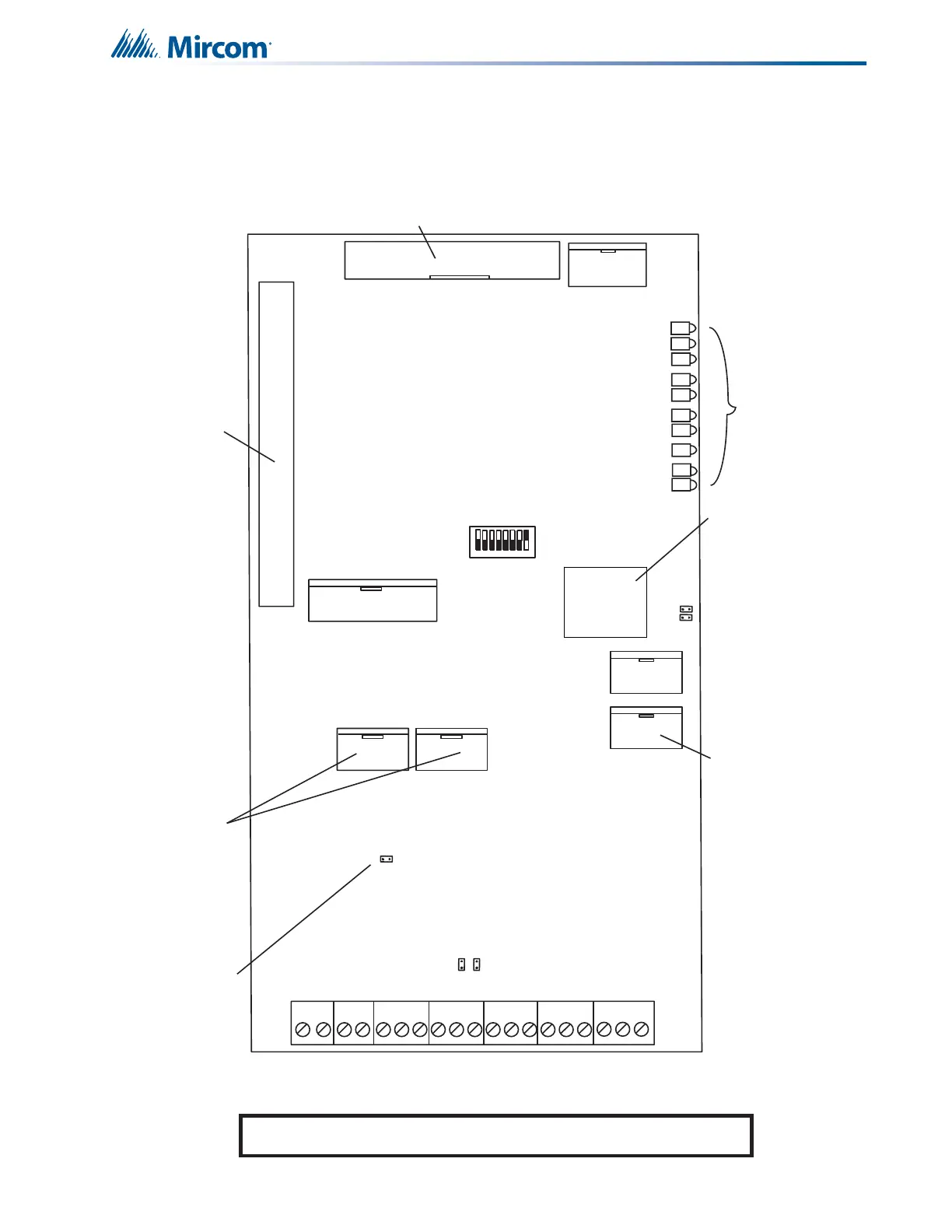
JW7
JW6
JW8
IN
OUT
JW4
JW5
P13
P11
P3 Network RS-485
P6 RS-485
P10 RS-485
P4 RS-232 Debug
ETHERNET
PORT
P7 AMPS Interface
P8 H_Speed Audio
Plugs into the
QMB-5000N
Backplane
Connect
RS-485 cable
from P3 on the
main re alarm
board to P6 IN
on this board
(daisy chain
fashion) and
from P10 OUT
to next main
re alarm
board or to
next ANC-4000
Connects to TNC-5000 Telephone
Network Controller Module
+ - + - + - S
+ - S + - L
+ - S+ - S
Alternate
Power
IN
G.A.
Input
IN
RS-485
PAGING BUS
MIC
PTT
IN OUT
SW1
1
8
ON
Heartbeat
COMM RX
COMM TX
Audio/CLASS D RX
Audio/CLASS D TX
Audio RX
Status Page Bus IN
Status Page Bus OUT
System OK
RESET/CPU Fail
Jumper JW6 is
normally open
Gain Level
Jumpers JW7 and JW8
are normally shorted
LEDs for
Information
P13 Ethernet
Port for Future Use
JW4 Jumper Factory
Use Only, Leave Open
JW5 Jumper Watch-
dog , Leave Shorted
P8 Connect to
main re alarm
board P16 if
using Digital
Audio and/or
Phone
NOTE: All connectors not shown on this drawing are for factory use only.
DIP Switch SW1 is factory set
at address one, SW1-8 ON.
Refer to Appendix C for all
DIP switch address settings.