125
32.1 QMT-5302NV Connections
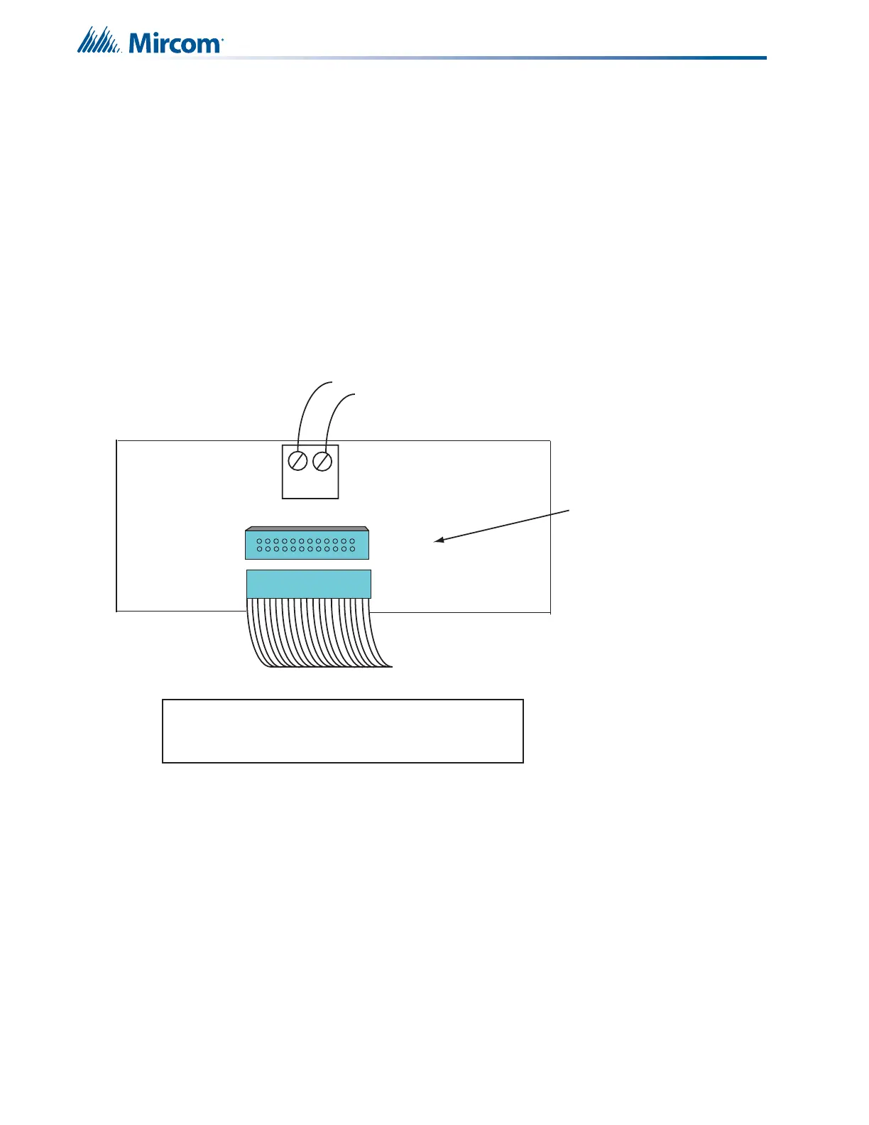
The connection required on the QMT-5302NV telephone board is the ribbon cable from the
previous display module to P1 or IN connector on the bottom center of the board and the OUT
connection goes to the IN connector of the next display board.
The master telephone positive and negative terminals (located on the back of the QMT-
5302NV) connect to the TNC-5000 Zone 1 postive and negative terminals with twisted pair
wires. Refer to Figure below for connector and terminal block locations of the QMT-5302NV.
- +
Connection from previous display
Connection to
Telephone
Selector Panel P1
or next display
IN
OUT
To TNC-5000 Telephone Zone 1
positive and negative terminals
(twisted pair wire)
P1
P2
Terminal connection located on the back of the
QMT-5302NV Network Master Fireghters’ Telephone