41
5.11.4 Isolator Mode
Jumpers for the Isolator Mode
JW2: Place jumper over pins 2 and 3 for the ability to connect an isolator on Zone 1.
JW3: Place jumper over pins 2 and 3 for the ability to connect an isolator on Zone 2.
JW4: Place jumper over pins 2 and 3 for the ability to connect an isolator on Zone 3.
JW5: Place jumper over pins 2 and 3 for the ability to connect an isolator on Zone 4.
J11: Wire these terminals to an alarm relay. These may be tapped if more signal modules are
used in this manner.
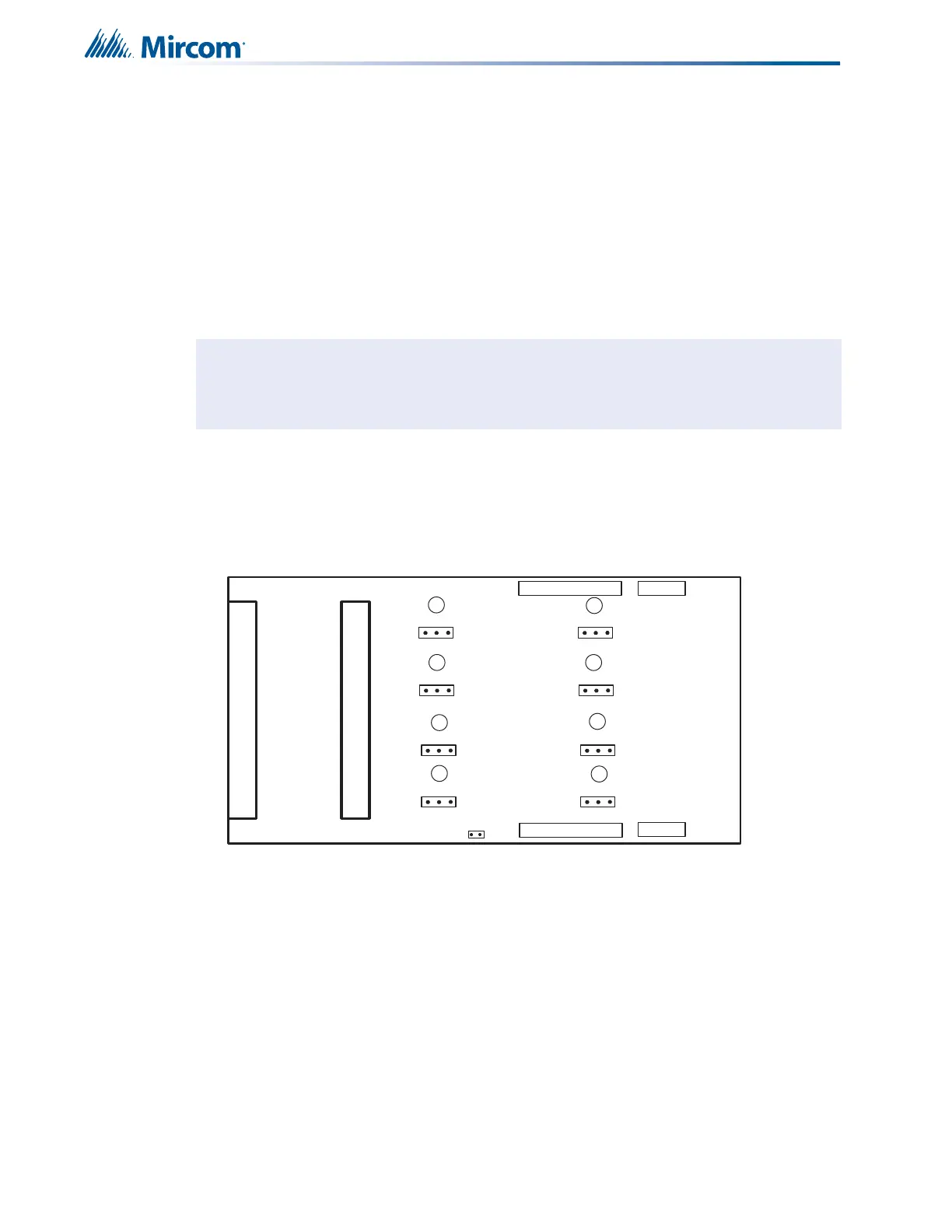
5.12 Hardwire Relay Adder Module (RM-1008A)
Figure 21 Hardwire Relay Adder Module (RM-1008A)
P2: Data cable to P6 or P5 of main fire alarm module, or to previous adder module.
P1: Data connector for next adder module.
P4: Power connector to P8 of main fire alarm module, or to previous adder module.
P3: Power connector for next adder module.
JW1: Remove continuity jumper if there are any more adder modules installed. If this is the
last module installed, leave JW1 on.
JP1-JP8: Move jumpers from pins 1 and 2 to 2 and 3 to connect relay commons between two
or more relays.
ATTENTION: Discard jumpers on zones that are not configured for isolators.
P1
P3
P4
FIELD WIRING TERMINALS
P2
JW1
FIELD WIRING TERMINALS
3 2 1
3 2 1
3 2 1
3 2 1
3 2 1
3 2 1
3 2 1
3 2 1
JP1
JP2
JP3
JP4
JP5
JP6
JP7
JP8
I1
I2
I3
I4
I5
I6
I7
I8