TX3 Card Access Installation Quick Reference
Version 2.1 for more information go to the CD, USB flash drive, or website and read the LT-980 Card Access System Manual
LT-6026
WWW.MIRCOM.COM
Card Access System Quick Reference
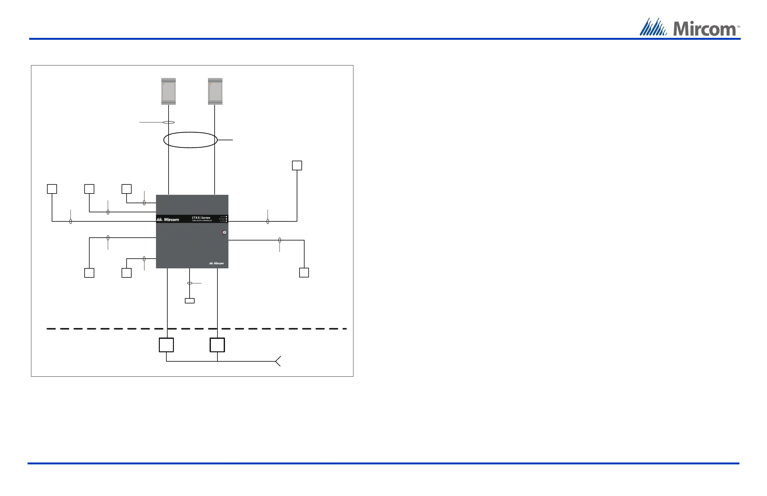
Single Panel Wiring
Basic Wiring
1
. Turn the controller power switch to OFF.
2
. Connect the card readers to Weigand terminal blocks.
3
. Connect the door strike or maglock to Output 1.
4
. Connect the controller supply.
5
. Set SW2 with a unique RS-485 network address.
6
. Turn the controller power switch to ON (a correctly wired controller will show a green AC LED).
Installation Prerequisites
Ensure there is a provision for a ground circuit. The Card Access System assembly must be grounded by a qualified
electrician. An improperly grounded unit can result in equipment malfunction and void the warranty.
Use the latest Card Access System controller firmware. Mircom periodically updates panel firmware and Configurator
Software to add features and correct any minor inconsistencies. For information about the latest firmware or software
visit the ‘Manuals and Downloads’ section of the Mircom website at www.mircom.com.
Before Starting the Configuration
Configure the system using the Configurator software using a USB or modem connection. Verify the following:
Ensure that the controller and all connected devices and components are fully operational.
Ensure the controller DIP Switches are set with a unique RS-485 network address.
Ensure the Configurator software is set with the correct controller RS-485 network address.
Ensure that your PC is set with the correct date and time.
•
•
•
•
•
•
To Start the Configuration
1
. Connect the PC to the controller using the USB port or modem connection.
2
. Launch the Configurator and select the correct controller you are connecting to (on the basis of name, panel label, panel
model, and network address).
3
. Click Connect. The connection icon appears in the Configurator tool bar.
4
. Ensure that the panel is configured with the correct date and time.
5
. Configure the Card Access system using the instructions in the LT-995 Configuration and Administration Manual.
Relay contact
RS-485
3 wires
18 AWG
22 AWG
Programmable outputs
Combined 1 amp output
12 Vdc
500 mA
1 pair
18 AWG
Door Sense
(Reader A )
Request to Exit
(Reader A )
1 pair
22 AWG
1 pair
22 AWG
1 pair
22 AWG
General
purpose input
1 pair
22 AWG
1 pair
22 AWG
6 ot 1 STUPTUO8 ot 1 STUPNI
Card Access
System
Electrical room
120 VAC
60HZ
Power
transformer
16VAC/40VA
PS-4 or PS-4P
Card Reader A
Power
transformer
AC or DC Door
strike supply
Maximum distance from the card reader
Use 20 AWG wire for 500 feet
Use 22 AWG or 24 AWG for 250 feet
Card Reader B
Configurable for the following actions
Request to Exit
(Reader B )
Door Sense
(Reader B )
OUTPUTS 7 to 8
Card readers supplied by Mircom
require shielded wiring. If other
card readers are used refer to their
reader wiring requirements.
Shield
The following figure shows the various controller connections
IMPORTANT
This document is for reference only and does not replace the existing documentation. For more detailed
information refer to the documentation on the CD, USB flash drive, or Mircom website
(www.mircom.com).
Wiring requirements
Install all transformers outside the Lobby Control Unit enclosure.
Unless specified otherwise, all wiring is a maximum length of 1000 ft. The RS-485 wiring maximum length is 4000 ft.
All units use the PS-4P transformer for the power supply. The door strike power supply depends on the door strike
power requirements.
•
•
•
 Loading...

