EasyManua.ls Logo

MirroCraft 1685 - Trolling System Wiring Diagrams; 12 Volt Trolling Motor Wiring Diagram; 24 Volt Trolling Motor Wiring Diagram

Default Icon
36 pages
Print Icon
To Next Page IconTo Next Page
To Previous Page IconTo Previous Page
Loading...
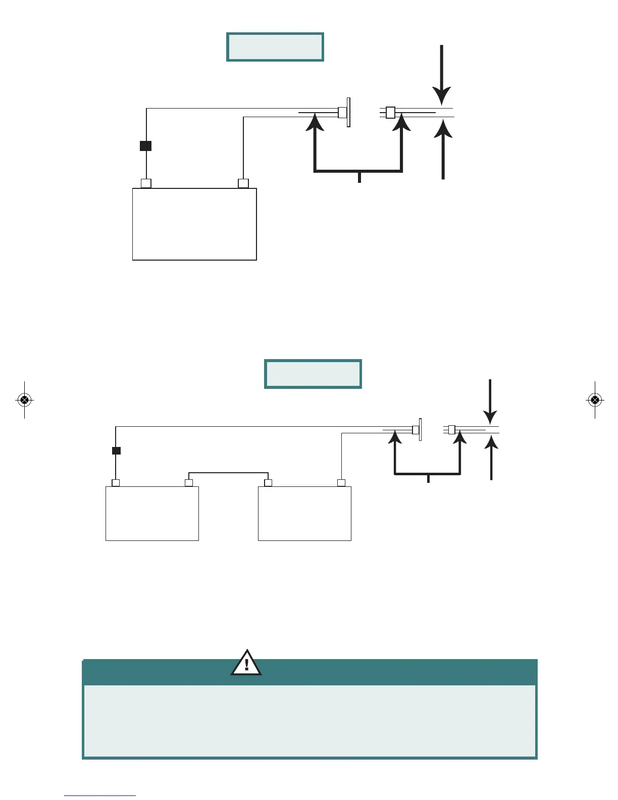
The two-wire trolling plug (Figure T-2) is a simple setup that allows you to hook
up a 12 volt trolling motor. The wiring is protected by a 40 amp circuit breaker
or fuse at the battery harness.
The 24 volt system (Figure T-3) requires 2 batteries hooked up in series with a
jumper wire between the two batteries. It is recommended that you contact your
dealer before installing.
21
WARNING:
Failure to hook up a trolling system properly could cause
damage to your boat and injury to yourself.
Battery
B
40 Amp
Circuit
Breaker
+
_
Black
Red
Orange Wire
DO NOT USE
Positive Wire
to Trolling
Motor (RED)
Negative Wire
to Trolling
Motor (BLACK)
Battery
A
+
_
Jumper Wire
Supplied by
Others
Battery
A
40 Amp
Circuit
Breaker
+
_
Black
Red
Orange Wire
DO NOT USE
Positive Wire
to Trolling
Motor (RED)
Negative Wire
to Trolling
Motor (BLACK)
Figure T-3
Figure T-2
69877_36635 4/4/11 10:17 PM Page 21