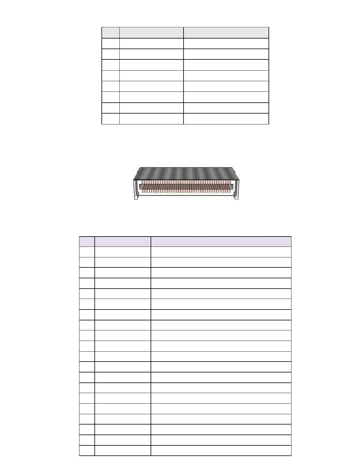
F i gu re 9 L V D S i n v e r t e r po w e r h e ade r
T
A B L E
9
8 -
PI N
L V D S
I N V E R T E R P O W E R H E A DE R PI N
-
O U T R E F E R E N C E
LVDS data header
F i gu re 10: P ro ce sso r f a n h ea d er
LVDS Channel A diff data output - positive
LVDS Channel A diff data output - negative
LVDS Channel A diff data output - positive
LVDS Channel A diff data output - negative
LVDS Channel A diff data output - positive
LVDS Channel A diff data output - negative
LVDS Channel A diff data output - positive
LVDS Channel A diff data output - negative
LVDS Channel B diff data output-positive
LVDS Channel B diff data output-negative
LVDS Channel B diff data output-positive
LVDS Channel B diff data output-negative
LVDS Channel B diff data output-positive
LVDS Channel B diff data output-negative
LVDS Channel B diff data output-positive
LVDS Channel B diff data output-negative
Selectable LCD power output
Selectable LCD power output
Selectable LCD power output